5 Installation
−13−
5.2 Installing the geared type, combination type
parallel shaft gearhead
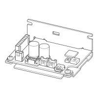
1. Open mounting holes in the mounting plate.
[Unit: mm (in.)]
Unit
model
ØA ØB C ØD
BLH015
43.8
(1.72)
16
(0.63)
8
(0.31)
4.5
(0.177)
BLH230
70
(2.76)
24
(0.94)
10
(0.39)
4.5
(0.177)
BLH450
94
(3.70)
34
(1.34)
13
(0.51)
6.5
(0.256)
ØB
C
4×ØD
ØA
BLH5100
104
(4.09)
40
(1.57)
18
(0.71)
8.5
(0.335)
ØB indicates the external dimension of the product.
Provide a hole with a diameter of “ØB +1 mm or more.”
Maximum applicable plate thickness
Unit model Maximum applicable plate thickness
BLH230 5 mm (0.20 in.)
BLH450 8 mm (0.31 in.)
BLH5100 12 mm (0.47 in.)
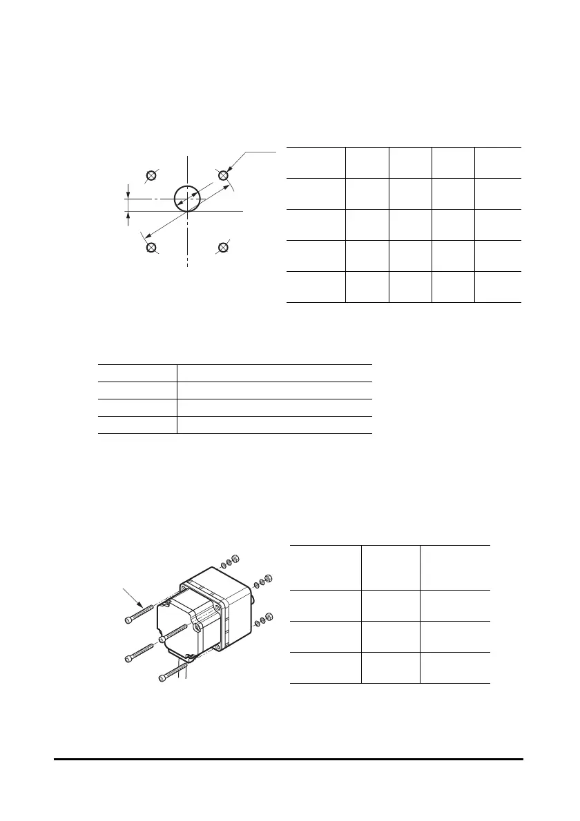
∗ The figures in the table apply when the supplied hexagonal socket head screw is used.
(BLH015 is not attached)
2. Install the supplied hexagonal socket head screw in the four mounting
holes you just opened and tighten the nuts until no gaps remain between
the motor and mounting plate.
• Combination type parallel shaft gearhead
Unit model
Nominal
thread
size
Tightening
torque
BLH230 M4
1.8 N·m
(15.9 lb-in)
BLH450 M6
6.4 N·m
(56 lb-in)
BLH5100 M8
15.5 N·m
(137 lb-in)
Hexagonal socket
head screws
 Loading...