5 Installation
−18−
Note
• Do not forcibly assemble the motor and gearhead. Also, do not let metal
objects or other foreign matters enter the gearhead. The pinion or gear of
the motor output shaft may be damaged, resulting in noise or shorter service
life.
• Do not allow dust to attach to the pilot sections of the motor and gearhead.
Also, assemble the motor and gearhead carefully by not pinching the O-ring
at the motor’s pilot section. If the O-ring is crushed or severed, grease may
leak from the gearhead.
5.4 Installing the round shaft type
Install the motor to a mounting plate of the following size or larger, so that the motor
case temperature will not exceed 90 °C (194 °F) (The BLH015 has no limitation on
the mounting plate size.).
Unit model Size of mounting plate Thickness • Material
BLH230 115×115 mm (4.53×4.53 in.)
BLH450 135×135 mm (5.31×5.31 in.)
BLH5100 200×200 mm (7.87×7.87 in.)
Thickness: 5 mm (0.20 in.)
Material: Aluminum
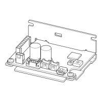
1. Open mounting holes in the mounting plate [Unit: mm (in.)].
Unit model ØA B ØC ØD
BLH015
48
(1.89)
33.94
(1.34)
37.6
+0.025
0
(1.4803
+0.0010
0
)
3.5
(0.138)
BLH230
70
(2.76)
49.5
(1.95)
54
+0.030
0
(2.1260
+0.0012
0
)
4.5
(0.177)
BLH450
94
(3.70)
66.47
(2.62)
73
+0.030
0
(2.8740
+0.0012
0
)
6.5
(0.256)
BLH5100
104
(4.09)
73.54
(2.90)
83
+0.035
0
(3.2677
+0.0014
0
)
8.5
(0.335)
ØC
B
B
ØA
ØD
ØC indicates the pilot diameter on the flange.
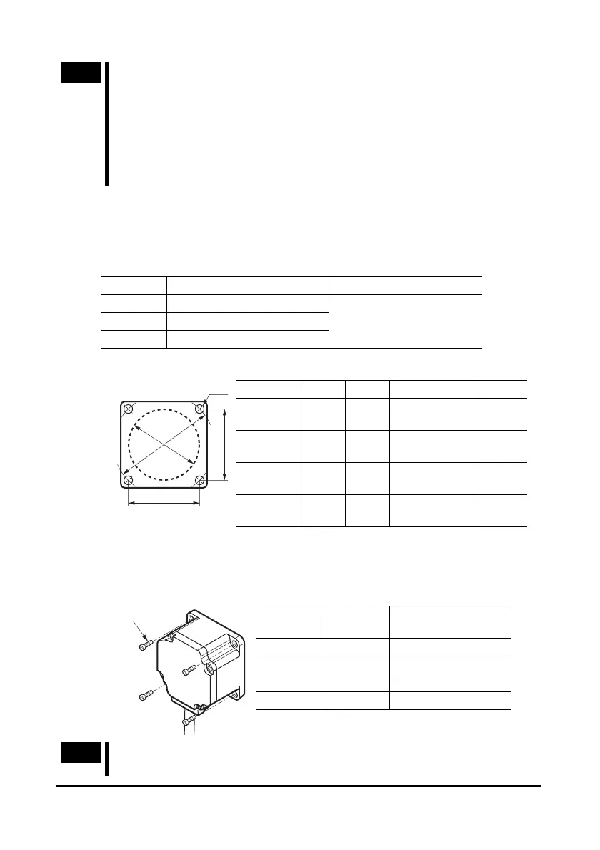
2. Install four bolts (not supplied) in the four mounting holes you just opened
and tighten the nuts until no gaps remain between the motor and
mounting plate.
Unit model
Nominal
thread size
Tightening torque
BLH015 M3 1 N·m (8.8 lb-in)
BLH230 M4 1.8 N·m (15.9 lb-in)
BLH450 M6 6.4 N·m (56 lb-in)
BLH5100 M8 15.5 N·m (137 lb-in)
Bolts
Note
Fit the boss on the motor mounting surface into a counterbore or through
pilot-receiving hole.
 Loading...