6 Connection
−29−
6 Connection
The following shows the method of connecting the motor and driver, power supply,
external potentiometer, earth connection method, an example of connection and I/O
signals.
6.1 Motor and driver connection
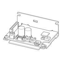
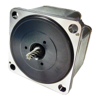
Insert the motor cable connector into the motor connector of the driver.
Unit model Motor connector
BLH015, BLH230, BLH450 CN3
BLH5100 CN3, CN4
Note
• Firmly insert the connector in position. Incomplete connection of the
connector may cause operation failure, or may damage the motor or driver.
• Do not push or pull the cable. Handle only the plastic connector instead.
Do not apply force in any direction other than that in which the connector is
inserted or pulled out. Improper application of force may damage the
connector and driver.
When extending the motor cable, use the accessory extension cable. The maximum
extension distance including the cable length of the motor itself should be 2 m
(6.6 ft.).
6.2 Connecting the power supply
Input power supply voltage is 24 VDC ±10%.
Insert the power supply cable connector into the driver power supply connector
(CN1). The specific connections vary depending on the outputs. If the supplied
power supply cable is not used, use a cable of the applicable wire size shown in the
table below.
Unit model Power supply cable size
BLH015, BLH230, BLH450 AWG22 (0.3 mm
2
) or more
BLH5100 AWG18 (0.75 mm
2
) or more
Note
• Sufficient care must be taken not to mistake the power supply polarity.
Connection with incorrect polarity may damage the driver.
• Do not route the driver power supply cable in the same conduit with other
power supply lines or motor cables.
• When you want to turn on the power supply again or pull out the motor cable
connector, do so 5 s or more after power supply has been turned off.

 Loading...


