5 Installation
−15−
Unit
model
Nominal
thread size
Tightening
torque
BLH230
BLH450
M2.6
0.4 N·m
(3.5 lb-in)
BLH5100 M3
0.6 N·m
(5.3 lb-in)
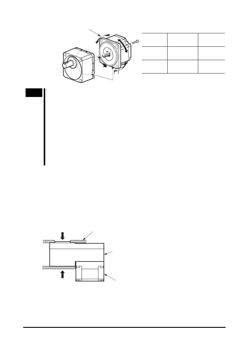
Pilot
Change the cable
position to a desired
90° direction.
Note
• Do not forcibly assemble the motor and gearhead. Also, do not let metal
objects or other foreign matters enter the gearhead. The pinion or gear of
the motor output shaft may be damaged, resulting in noise or shorter service
life.
• Do not allow dust to attach to the pilot sections of the motor and gearhead.
Also, assemble the motor and gearhead carefully by not pinching the O-ring
at the motor’s pilot section. If the O-ring is crushed or severed, grease may
leak from the gearhead.
• The hexagonal socket head screws (2 pcs.) assembling the motor and
gearhead are affixing the motor and gearhead only temporarily. When
installing the gearhead, be sure to use the supplied four hexagonal socket
head screws.
5.3 Installing the combination type hollow shaft flat
gearhead
A gearhead can be installed by using either its front or rear side as the mounting
surface. Install the supplied hexagonal socket head screw in the four mounting holes
you opened and tighten the nuts until no gaps remain between the motor and
mounting plate. Also, attach the supplied safety cover to the hollow output shaft on
the end opposite from the one where the load shaft is installed.
Front
Mounting plate
Gearhead
Motor
Rear
 Loading...