3.Junior User Guidebook
How to Implement the Probe Compensation
When connect the probe with any input channel for the first time, make this
adjustment to match the probe with the input channel. The probe which is not
compensated or presents a compensation deviation will result in the
measuring error or mistake. For adjusting the probe compensation, please
carry out the following steps:
1. Set the attenuation coefficient of the probe on the menu as 10X and that of
the switch in the probe as 10X (see "How to Set the Probe Attenuation
Coefficient" on P11), and connect the probe with the CH1 channel. If a
probe hook tip is used, ensure that it keeps in close touch with the probe.
Connect the probe tip with the signal connector of the probe compensator
and connect the reference wire clamp with the ground wire connector of
the probe connector, and then push the Autoset button on the front panel.
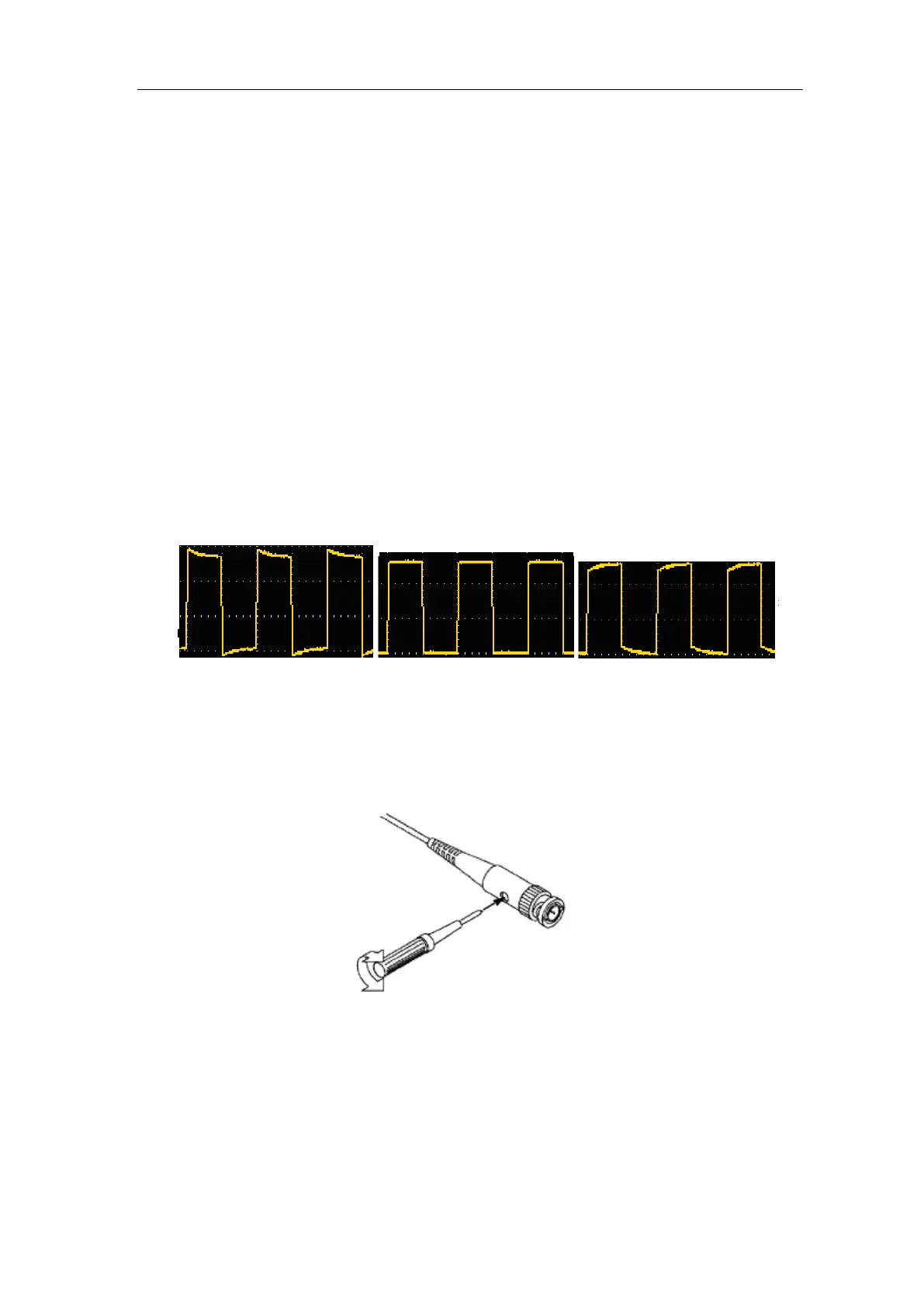
2. Check the displayed waveforms and regulate the probe till a correct
compensation is achieved (see Figure 3-6 and Figure 3-7).
Overcompensated Compensated correctly Under
compensated
Figure 3-6 Displayed Waveforms of the Probe Compensation
3. Repeat the steps mentioned if needed.
Figure 3-7 Adjust Probe
How to Set the Probe Attenuation Coefficient
The probe has several attenuation coefficients, which will influence the vertical
scale factor of the oscilloscope.
To change or check the probe attenuation coefficient on the menu of
 Loading...