4.Advanced User Guidebook
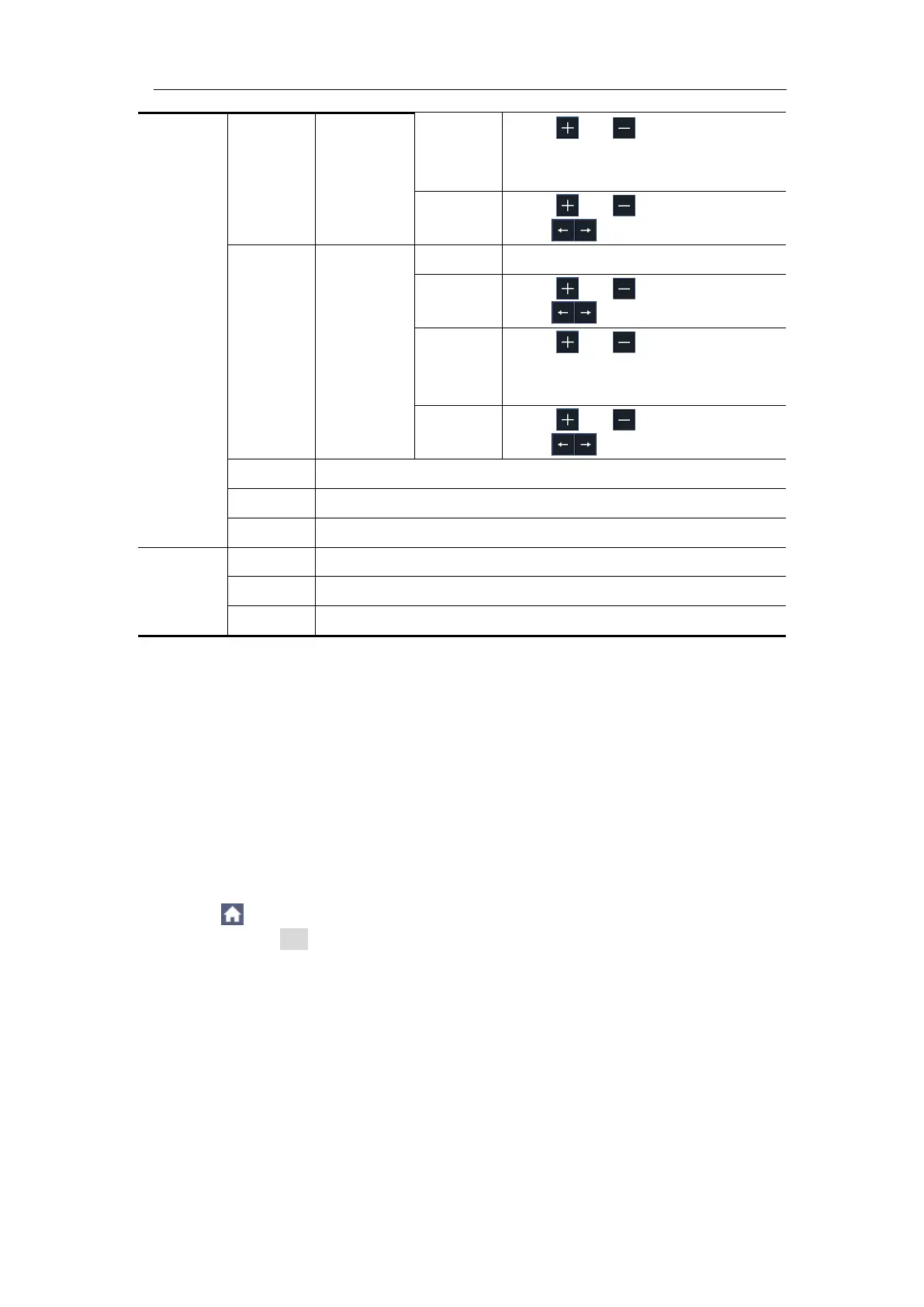
Click or to set the
number of bytes. The range is 1
to 8.
Click or to set value,
click to move cursor.
Select Standard or Extend.
Click or to set value,
click to move cursor.
Click or to set the
number of bytes. The range is 1
to 8.
Click or to set value,
click to move cursor.
Trigger on the end frame of the data frame.
Trigger on Bit Stuffing Error.
Acquire waveform even no trigger occurred
Acquire waveform when trigger occurred
When trigger occurs, acquire one waveform then stop
Bus Decoding (Optional)
1. UART Decoding
To decode UART signal:
(1) Connect the UART signal to the signal input channel of the oscilloscope.
(2) Adjust to the proper time base and voltage division.
(3) In trigger menu, select Bus trigger, and select bus type as UART, set
parameters based on the characteristics of the signal, trigger the signal
correctly and obtain stable display. Refer to "UART Trigger" on page 38.
(4) Click to call up the menu panel. Click the Decode softkey on panel to
switch to the ON state. Select bus type as UART, set parameters based on
the characteristics of the signal. When the parameters are set correctly,
the information carried by the signal will be displayed.
Tip: If there are repetitive menu items in both trigger menu and decoding menu,
you can set anyone of them, the other will be changed synchronously.
Note:
Use the upper knob to adjust the thresholds of bus trigger and bus
decoding.
When decoding, if "Parity" is not set to "None", and the check bit error is
detected, two red error marks will be displayed in the corresponding
 Loading...