EasyManua.ls Logo

Parker COMPAX-M /-S (L) User Manual

Parker COMPAX-M /-S (L)
242 pages
To Next Page IconTo Next Page
To Previous Page IconTo Previous Page
Page #160 background imageLoading...
Page #160 background image
Operating Instructions
COMPAX-M / -S
RS232 interface
160
8.6.3 RS232 interface
You can communicate with COMPAX via an RS232 interface on a PC. The
following functions are available.
Direct command input and execution in on-line mode.
Read status values.
Read and write program data records (the complete stock of commands is
available here).
Read and write (password protected) parameters.
Transmit control instructions.
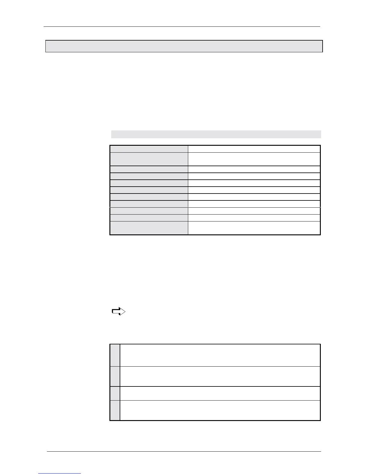
8.6.3.1 Interface description
Interface RS 232
Baud rate: 9600* or 4800 (selected with P19)
COMPAX 1000SL: fixed setting 9600
Word length: 8 bit
Stop bit: 1
Parity: none
Hardware handshake: yes (RTS,CTS)
Software handshake: XON, XOFF (can be selected using P20)
Entry buffer: error string, max. 30 characters
Output buffer: status string, max. 30 characters
Data format: ASCII
End sign: C
R
(carriage return) or C
R
L
F
(carriage return, line
feed)
* Default setting; simultaneously press the three front plate buttons while switching
on to set COMPAX to 9600 Baud.
all displayable ASCII characters
any inserted spaces
a function sign, if nec. ($, ?, !)
C
R
(carriage return) for storing the command in the intermediate memory. If no
function signs have been transmitted, the command is accepted and executed if
necessary (see next page).
L
F
(line feed) has no meaning to COMPAX
COMPAX only receives a command if a previously transmitted command
was answered with C
R
L
F
>.
if the syntax is error-free with C
R
L
F
> or the required response and C
R
L
F
>
if there are errors, depending on the contents of P20
$
Automatic "Position reached" message
1. only applies to POSA and POSR
2. COMPAX transmits: $
C
R
L
F
> when the position is reached.
,
Interpreting and storing commands
COMPAX stores the instruction in the intermediate memory (capacity: one
instruction) without executing it.
?
Echo
COMPAX sends the data received with C
R
L
F
>.
!
Executing commands
Whenever a "!" occurs, the instruction is executed from the intermediate
memory.
These function signs can be attached to any instruction.
Example: POSA 100 $ C
R
L
F
COMPAX moves and responds once position 100 is reached with: $
C
R
L
F
>
Interface
parameters
COMPAX receives
COMPAX
responds:
Meaning of
function signs

Table of Contents

Question and Answer IconNeed help?

Do you have a question about the Parker COMPAX-M /-S (L) and is the answer not in the manual?

Parker COMPAX-M /-S (L) Specifications

General IconGeneral
ModelCOMPAX-M /-S (L)
Protection ClassIP20
SeriesCOMPAX
Input Voltage24 V DC
Communication InterfacesCANopen
Operating Temperature0°C to +45°C
Operating Temperature Range0°C to +45°C
Storage Temperature Range-20°C to +70°C

Summary

Unit assignment

General dangers

General dangers when safety instructions are not complied with, including hazards from energized, moving, or rotating parts.

Safe working practices

Guidelines for safe operation, emphasizing trained staff and adherence to safety instructions.

Special safety instructions

Specific safety instructions for unit operation, including checks and precautions.

Conditions of warranty

Conditions of warranty

Conditions for warranty, including not opening the unit and no unauthorized alterations.

COMPAX CD

Switch-on status

Configuration when supplied

Describes the default configuration of COMPAX units upon delivery, including parameter P149 settings.

Commissioning

Details the commissioning process, including LED meanings for COMPAX-M/-S, mains modules, and COMPAX 1000SL.

Equipment replacement

Equipment replacement

Procedure for copying COMPAX settings to a new unit for software versions V2.0 and V2.0.

Conditions for usage

Conditions for usage

Peripheral conditions for CE-compliant operation, including power filters and cable lengths.

Start-up manual

7.1 Overview:

Provides an overview of the start-up process, including required components and unit technology.

7.2 COMPAX-M unit features

Details the features of COMPAX-M units, including connector and terminal assignments.

7.3 Mains module NMD10/NMD20

Describes the NMD10/NMD20 mains module, including overview, dimensions, and technical data.

7.4 COMPAX 35XXS unit features

Details the features of COMPAX 35XXS units, including plug and connection assignments.

7.5 COMPAX 25XXS unit characteristics

Describes the characteristics of COMPAX 25XXS units, including connector and connection assignments.

7.6 COMPAX 45XXS/85XXS unit characteristics

Describes the characteristics of COMPAX 45XXS/85XXS units, including plug and connection assignments.

7.7 COMPAX 1000SL Unit characteristics

Details the characteristics of the COMPAX 1000SL unit, including connector and terminal assignments.

7.8 Connections to the motor

Provides information on connecting motors, including resolver and SinCos systems, and additional brake control.

7.9 Interfaces

Details the various interfaces available on COMPAX units, including digital I/O and serial interfaces.

7.10 Technical data

Provides essential technical data for COMPAX units, covering power, supply voltage, and protection.

Operating Instructions

8.1 Overview:

Provides a general overview of the COMPAX digital positioning system and its main features.

8.2 Configuration

Covers the configuration process for COMPAX units, including front plate operation and settings.

8.3 Configuration via PC using "ServoManager"

Guides on installing and using ServoManager for configuring COMPAX and synchronous motors.

8.4 Positioning and control functions

Details positioning commands, control functions, and programming structures for COMPAX.

8.5 Optimization functions

Explains how to optimize COMPAX performance, including parameters for dynamic adjustment.

8.6 Interfaces

Describes the various interfaces available on COMPAX units for data exchange and control.

Accessories and options

9.1 System concept

Outlines the COMPAX system concept, components, and expandable system elements.

9.2 Overview

Provides an overview of COMPAX system components and associated cables for drives and interfaces.

9.3 Motors

Information regarding supported motors, including EMD and linear motors for COMPAX.

9.4 HAUSER linear actuators

Details HAUSER linear actuators, including available cross sections and drives.

9.5 Data interfaces

Describes available data interfaces like RS232 and various bus systems.

9.6 Process interfaces

Details process interfaces such as encoder, absolute value sensors, and SinCos systems.

9.7 Accessories

Lists available accessories for COMPAX, including control panels, modules, and filters.

Appendix

10.1 Status values of the standard unit (COMPAX XX00)

Lists and explains status values for the standard COMPAX XX00 unit, including actual and diagnosis values.

10.2 Additional COMPAX measuring quantites

Details additional COMPAX measuring quantities and signal indicators for optimization display.

10.3 COMPAX parameter

Provides information on COMPAX parameters, including VP parameters and standard parameter groups.

10.4 Error handling and error messages

Covers error handling procedures and lists error messages with their causes and actions.

Application examples

11.1.1 Overview

Provides an overview of application examples, including external data record selection and mark-referenced positioning.

11.1.2 External data record selection

Details an application example for external data record selection using a BCD switch.

11.1.3 Mark-referenced positioning

Describes an application example for mark-referenced positioning for cutting plates.

11.1.4 Speed step profiling / comparator switching points

Illustrates an application example of speed step profiling and comparator switching points for bore spindle control.

11.1.5 SPEED SYNC

Explains an application example for SPEED SYNC, involving carton transfer between conveyor belts.

11.1.6 Speed control mode

Describes an application example for speed control mode, used for centrifuge operation.

11.1.7 Fast start

Details an application example for fast start, used for material feeding in a stamping machine.

11.1.8 Implementing a torque controller

Explains two options for implementing a torque controller using speed or position control modes.

Index

Related product manuals