COMPAX-M unit features
Connector and terminal assignment
17
Unit
hardware
Connector
assignment / cable
Technical dataConfigurationPositioning and
control functions
Optimization
functions
InterfacesAccessories /
options
StatusParameterError list
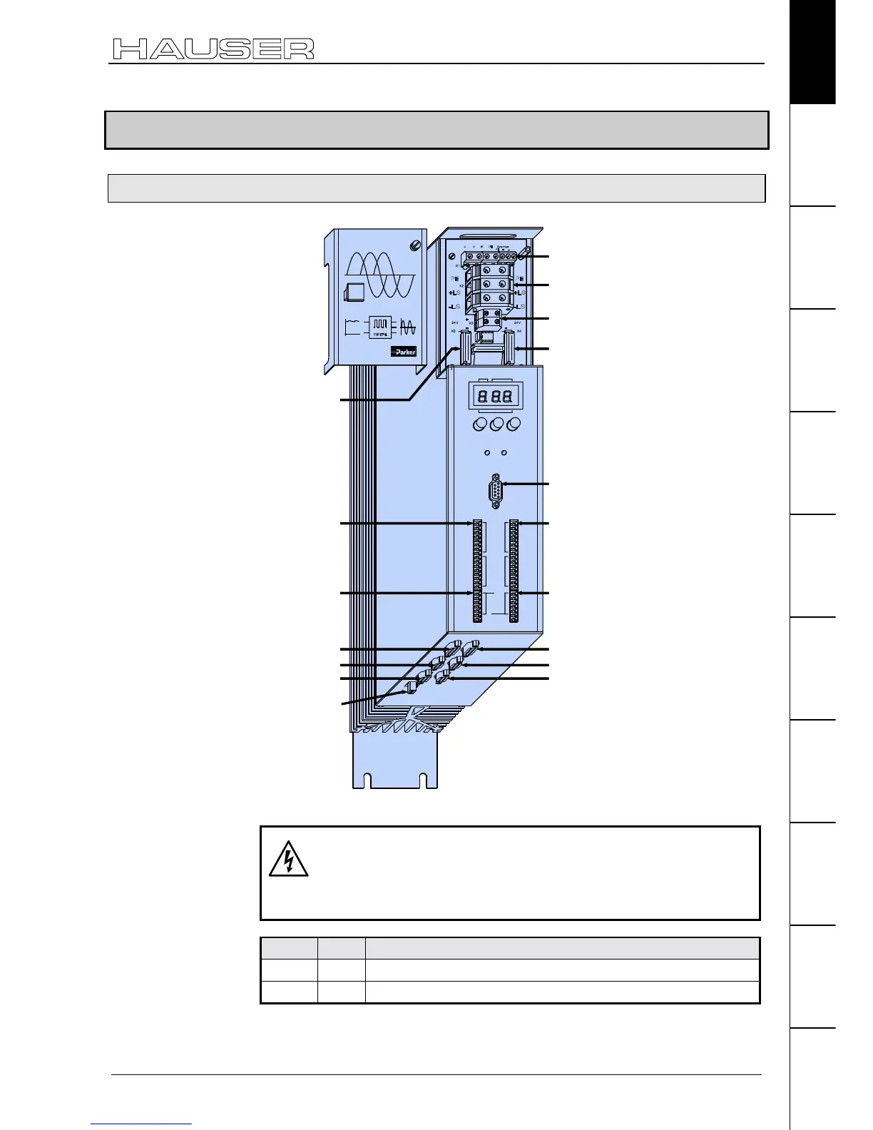
7.2 COMPAX-M unit features
7.2.1 Connector and terminal assignment
X2 intermediate loop
power connections
X3 24V control voltage
X4 control- and status
signals / bus signals
or short circuit plug
X13 Encoder
COMPAX-M
X6
Inp u t
Output
Status
Value
+- Enter
Ready Error
RS 232
Test
Control
X8 X10
X9 X11
Number
X1 motor
X5 control- and
status- signal
bus-signals
input
X6 RS232
X10 Input / Output
X11 Control
X8 Input
/ Output
X9 Test
X12 resolver
X14 HEDA
X16 absolute
encoder
X18 fan
X15 HEDA
X17 initiators
Before wiring up, always de-energize the unit.
Even once the mains supply has been switched off,
dangerous levels of voltage can remain in the system for
up to 5 min.
LED Color Meaning, when switched on
Ready green 24V DC present and initialization complete
Error red COMPAX - fault (I1...E56) present.
Meaning of LEDs on
front plate

 Loading...


