6
SUPERFLO® VST, SUPERFLO
®
VS and SUPERMAX® VS Variable Speed Pumps Installation and User’s Guide
External Control via Digital Inputs
When paired with either the Digital Input Wiring Kit (P/N 353129Z - Almond) or RS-485 Automation Wiring Kit
(P/N 356324Z - Black), the pump can be externally controlled by digital input signals.
Note: If the pump is manually stopped using the Start/Stop button, the pump will not run until the Start/
Stop button is pressed. If the Start/Stop LED is
illuminated, the pump is active and can be controlled
externally.
The communication cable provided with these kits
features a watertight connection that plugs into the Pump
Com Port (Figure 5 on page 5). The opposite end of
the cable has either 6 or 8 conductors dened in Table 1.
A trigger signal is required to externally control the pump
via digital inputs. This required output signal can to be
provided in one of the following ways:
• By the pump drive. Refer to Using the Pump's
Output Signal.
• By an external low voltage signal. Refer to Using an
External Input Signal on page 7.
Using the Pump's Output Signal
1. Route the communication cable from the Pump Com Port (Figure 5 on page 5) to the control system wiring
compartment.
2. Ensure the cable reaches all necessary terminals and cut to the necessary length.
3. Strip the cable 3/4" (19 mm).
4. Strip all 24 AWG conductors 1/2" (13 mm).
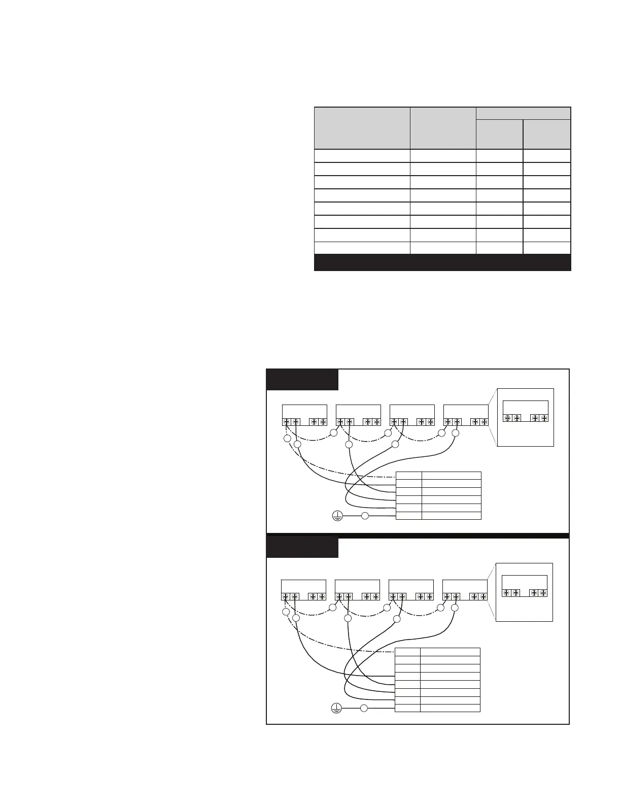
5. If using Digital Input Wiring Kit (P/N
353129Z - Almond): Wire communication
cable to control system as shown in Figure
6A.
If using RS-485 Automation Wiring
Kit (P/N 356324Z - Black): Wire
communication cable to control system as
shown in Figure 6B.
Note: Unused conductors should be cut
o and terminated according to local and
national electrical codes.
6. Using the pump keypad, program the
pump's internal clock. Refer to Setting the
Clock and Pump Address on page 8.
7. Using the pump keypad, program SPEED 1
to 0 RPM and a duration of 24 hours. Refer
to Programming Custom Schedules on
page 9.
8. Using the pump keypad, disable priming.
Refer to Priming on page 11.
9. When ready to start the pump, place the
pump into External Control Only mode.
Refer to External Control Only Mode on
page 7.
10. Plug the communication cable into the
Pump Com Port.
Signal Description Signal Range
Wire Color
Wiring Kit
353129Z
(Almond)
Wiring Kit
356324Z
(Black)
+5V Output for Digital Inputs 0-20mA Red Red
RS-485 A -7V to +12V - Yellow
RS-485 B -7V to +12V - Green
SPEED 1 Digital Input 0, 5-30V AC/DC Green White
SPEED 2 Digital Input 0, 5-30V AC/DC Yellow Blue
SPEED 3 Digital Input 0, 5-30V AC/DC Orange Orange
QUICK CLEAN Digital Input 0, 5-30V AC/DC Brown Brown
Common Ground 0V Black Black
Table 1
RELAY 1 RELAY 2RELAY 3RELAY 4
RELAY
LINE 1
LOAD 1
LOAD 2
LINE 2
POWER RELAY (DPST)
RED (R)
OUTPUT FOR D.I. TRIGGER
GREEN (G) SPEED 1 DIGITAL INPUT
YELLOW (Y) SPEED 2 DIGITAL INPUT
ORANGE (O)
SPEED 3 DIGITAL INPUT
BROWN (B) SPEED 4 DIGITAL INPUT
BLACK (K)GROUND
G
R
R
R
R
O
Y
B
K
RELAY 1 RELAY 2RELAY 3RELAY 4
RELAY
LINE 1
LOAD 1
LOAD 2
LINE 2
POWER RELAY (DPST)
W
R
R
R
R
O
Bl
B
K
RED (R)
OUTPUT FOR D.I. TRIGGER
WHITE (W) SPEED 1 DIGITAL INPUT
BLUE (Bl) SPEED 2 DIGITAL INPUT
ORANGE (O)
SPEED 3 DIGITAL INPUT
BROWN (B) SPEED 4 DIGITAL INPUT
BLACK (K)GROUND
GREEN (G)NOT USED
YELLOW (Y) NOT USED
Figure 6A
Figure 6B
Digital Input Wiring Kit
(P/N 353129Z - Almond)
RS-485 Automation Kit
(P/N 356324Z - Black)
 Loading...