SUPERFLO® VST, SUPERFLO
®
VS and SUPERMAX® VS Variable Speed Pumps Installation and User’s Guide
5
External Control via RS-485
The following instructions only apply to SuperFlo
®
VST and SuperMax
®
VS pumps manufactured after
10/15/20. For all other pumps, refer to External
Control via Digital Inputs on page 6.
These pumps can be controlled from certain Pentair
control systems, via an RS-485 signal, when paired with
the RS-485 Automation Wiring Kit (P/N 356324Z - Black).
Note: IntelliConnect
®
Control and Monitoring
Systems can NOT externally control this pump via
RS-485. The pump will need to be connected via
digital inputs. Refer to External Control via Digital
Inputs on page 6.
Note: If the pump is manually stopped using the
Start/Stop button, the pump will not run until the
Start/Stop button is pressed. If the Start/Stop
LED is illuminated, the pump is active and can be
controlled externally.
Only the GREEN and YELLOW conductors will be used
to wire the pump for external control via RS-485. See
Figure 4.
Control System Pump Settings
Pump Type: Variable Speed (VS)
Control systems with older rmware may require the
pump be designated "IntelliFlo VS".
This pump will not process control system commands
if designated a Variable Flow (VF) or Variable Speed/
Flow (VSF) pump.
Pump Address: 1 or 2
Ensure the assigned pump address matches the pump
address in the control system. Refer Setting the Clock
and Pump Address, page 8.
Refer to the control system manual for more information
on connecting and programming your pump.
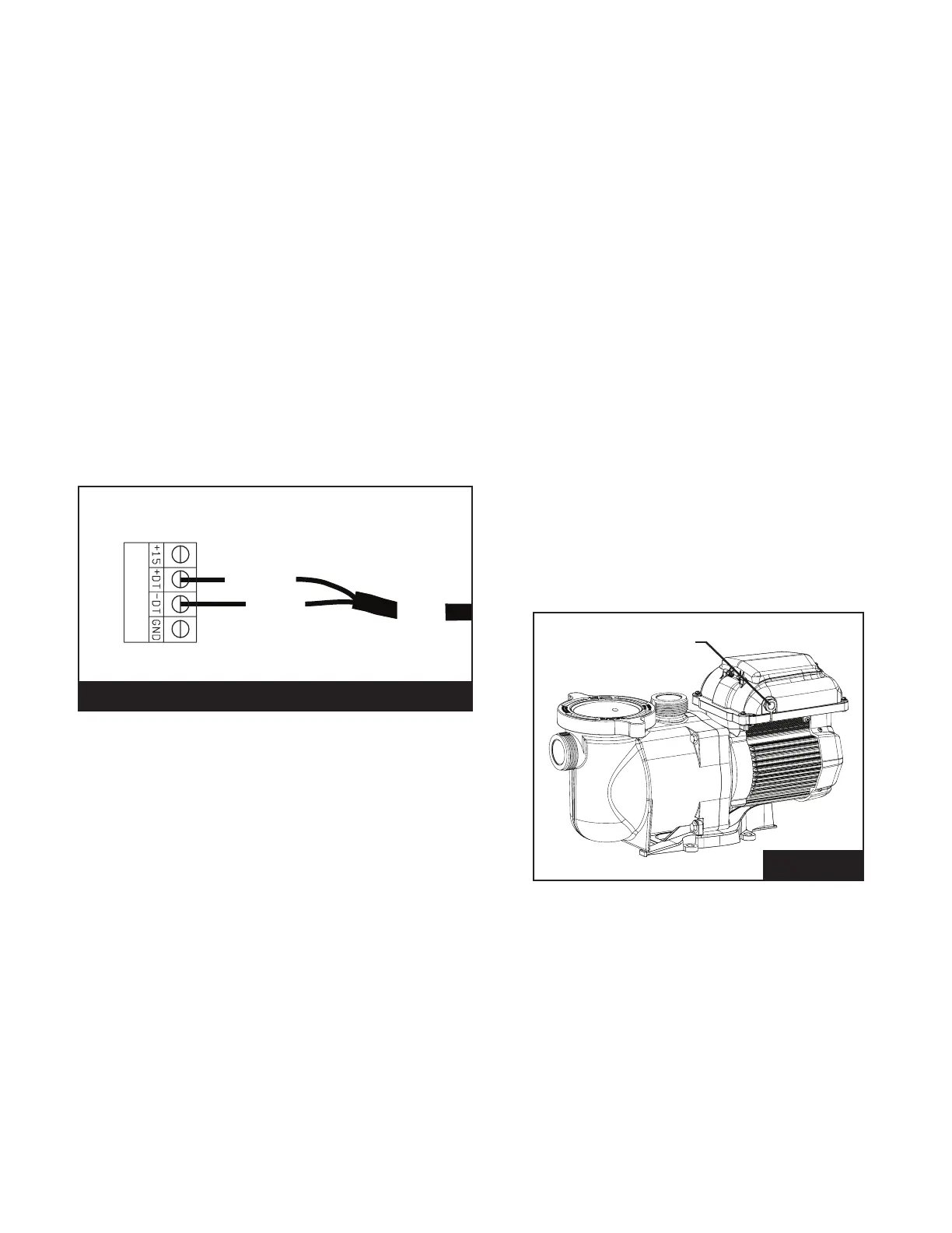
Pump Com
Port
Figure 5
TO WIRE FOR EXTERNAL CONTROL USING RS-485:
1. Route the communication cable from the Pump
Com Port (Figure 5) to the control system wiring
compartment.
2. Ensure the cable reaches all necessary terminals
and cut to the necessary length.
3. Strip the cable 3/4" (19 mm).
4. Strip the 24 AWG GREEN and YELLOW conductors
1/2" (13 mm).
5. Cut back and terminate unused conductors
according to local and national electrical codes.
6. Connect YELLOW and GREEN conductors to the
control system as shown in Figure 4.
7. Program the pump's internal clock. Refer to Setting
the Clock and Pump Address on page 8.
8. Program SPEED 1 to a speed of 0 RPM and
duration of 24 hours. Refer to Programming Custom
Schedules on page 9.
9. Disable priming at the pump. Priming duration and
speeds will be controlled by the control system.
Note: If priming is not disabled at the pump,
priming will be continue to be controlled by the
pump. Refer to Priming on page 11.
10. Plug the communication cable into the Pump Com
Port (Figure 5).
YELLOW
GREEN
Automation System
COM Port
Note: Only the GREEN and
YELLOW wires will be used. All
other wires should be cut off at the
cable sheath.
From
Pump
4
3
2
1
Figure 4
RS-485 Automation Kit (P/N 356324Z - Black)
 Loading...