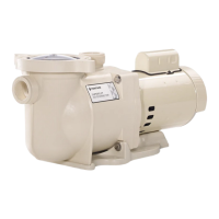
SUPERFLO® VST, SUPERFLO
®
VS and SUPERMAX® VS Variable Speed Pumps Installation and User’s Guide
3
INSTALLATION
Fittings and Valves
1. Do not install 90° elbows directly into suction port.
2. Flooded suction systems should have gate
valves installed on suction and discharge pipes
for maintenance, however, the suction gate valve
should be no closer than ve times the suction pipe
diameter as described in this section.
3. Use a check valve in the discharge line when
using this pump for any application where there is
signicant height to the plumbing after the pump.
4. Be sure to install check valves when plumbing in
parallel with another pump. This helps prevent
reverse rotation of the impeller and motor.
Only a qualied plumbing professional should install the pump. Refer to IMPORTANT SAFETY INSTRUCTIONS on
page i-ii for additional installation and safety information.
Location
Note: Do not install this pump within an outer enclosure
or beneath the skirt of a hot tub or spa unless marked
accordingly.
Note: Ensure that the pump is mechanically secured to
the equipment pad.
ENSURE THE INSTALL LOCATION MEETS THE
FOLLOWING REQUIREMENTS:
1. Install the pump as close to the pool or spa as
possible. To reduce friction loss and improve
eciency, use short, direct suction and return piping.
2. Install a minimum of 5 ft. (1.5 m) from the inside wall
of the pool and spa. Canadian installations require
a minimum of 9.8 ft. (3 m) from the inside wall of the
pool.
3. Install the pump a minimum of 3 ft. (0.9 m) from the
heater outlet.
4. Do not install the pump more than 10 ft. (3.1 m)
above the water level.
5. Install the pump in a well ventilated location
protected from excess moisture (i.e. rain gutter
downspouts, sprinklers, etc.).
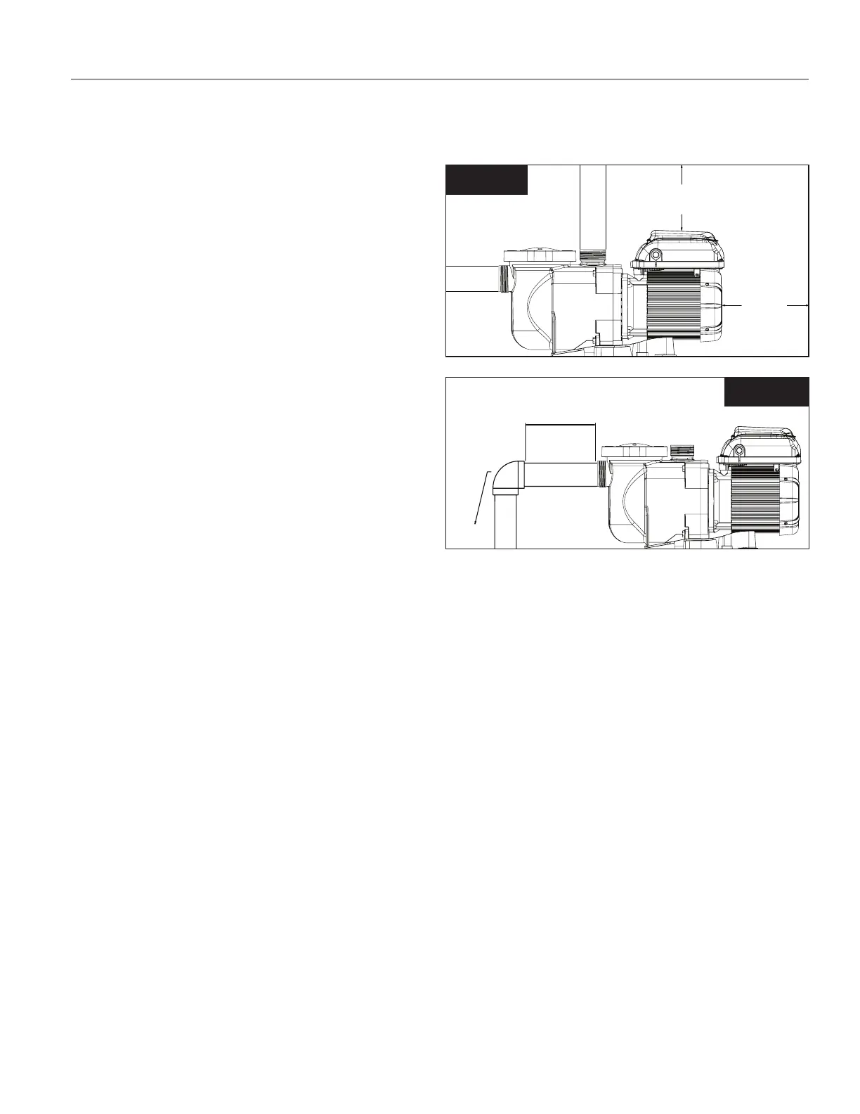
6. Install the pump with a rear clearance of at least
3 inches (7.6 cm) so that the motor can be removed
easily for maintenance and repair. See Figure 1.
Piping
1. For improved pool plumbing, it is recommended to
use a larger pipe size.
2. Piping on the suction side of the pump should be the
same or larger than the return line diameter.
3. Plumbing on the suction side of the pump should be
as short as possible.
4. For most installations Pentair recommends installing
a valve on both the pump suction and return lines
so that the pump can be isolated during routine
maintenance. However, we also recommend that a
valve, elbow or tee installed in the suction line should
be no closer to the front of the pump than ve (5)
times the suction line diameter. See Figure 2.
Example: A 2.5" pipe requires a 12.5" (31.8 cm)
straight run in front of the suction port. This will help
the pump prime faster and last longer.
Note: DO NOT install 90° elbows directly into the
suction or discharge ports.
5 x SUCTION PIPE DIAMETER
ELBOW
Figure 2
3 IN.
MINIMUM
Figure 1
6 IN. (15.2 CM)
MINIMUM
 Loading...