SUPERFLO® VST, SUPERFLO
®
VS and SUPERMAX® VS Variable Speed Pumps Installation and User’s Guide
7
Using an External Input Signal
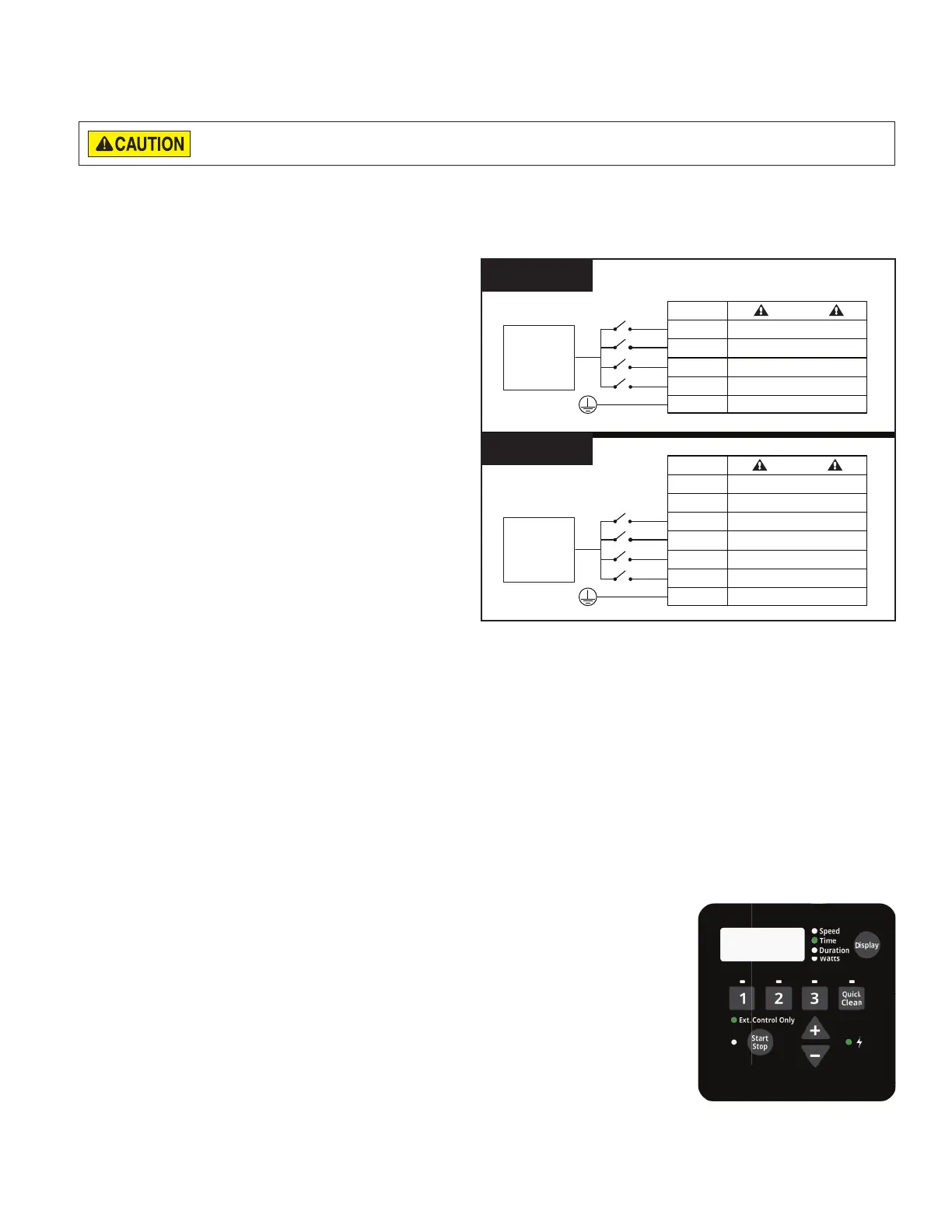
When using an externally supplied low voltage signal for external control, input voltage must be within 5-30V AC/DC.
The wiring kit's RED wire is only intended to carry the +5V output signal from the drive and will NOT be used.
The +5V signal (RED wire) is output from the drive only and should never be wired to another power supply. Improper wiring
will damage the drive.
The external output signal can be regulated by switches or relays to initiate a desired pump function. If multiple digital
inputs are active, the priority is: QUICK CLEAN > SPEED 3 > SPEED 2 > SPEED 1.
TO WIRE FOR EXTERNAL CONTROL USING AN EXTERNAL INPUT SIGNAL:
1. Route the communication cable from the Pump
Com Port (Figure 5 on page 5) to the control
system wiring compartment.
2. Ensure the cable reaches all necessary terminals
and cut to the necessary length.
3. Strip the cable 3/4" (19 mm).
4. Strip all 24 AWG conductors 1/2" (13 mm).
5. If using Digital Input Wiring Kit (P/N 353129Z
- Almond): Wire communication cable to control
system as shown in Figure 7A.
If using RS-485 Automation Wiring Kit (P/N
356324Z - Black): Wire communication cable to
control system as shown in Figure 7B.
Note: Unused conductors should be cut o
and terminated according to local and national
electrical codes.
6. Using the pump keypad, program the pump's
internal clock. Refer to Setting the Clock and Pump
Address on page 8.
7. Using the pump keypad, program SPEED 1 to a speed of 0 RPM and duration of 24 hours. Refer to Programming
Custom Schedules on page 9.
8. Using the pump keypad, disable priming. Refer to Priming on page 11.
9. When ready to start the pump, place the pump into External Control Only mode. Refer to External Control Only
Mode.
10. Plug the communication cable into the Pump Com Port.
External Control Only Mode
External Control Only mode will only allow the pump to run from external controls/inputs. When this mode is active
the programmed pump schedule is deactivated, and user speed requests from the keypad will not be accepted. If the
pump is stopped a user can still program the speeds for all four SPEED buttons.
Note: The following steps are required if controlling the pump via digital inputs, but
optional if controlling via RS-485. The pump will prioritize RS-485 commands over
digital input commands.
TO ENABLE/DISABLE EXTERNAL CONTROL ONLY MODE:
1. If the pump is running or Start/Stop LED is illuminated, press the Start/Stop
button to stop the pump.
2. Press and hold the Start/Stop button for 10 seconds to enable/disable External
Control Only mode.
The Ext. Control Only LED will illuminate if enabled. See Figure 8.
3. Press the Start/Stop button to start the pump.
9
:
00
Pm
Figure 8
RED
GREEN SPEED 1 DIGITAL INPUT
YELLOW SPEED 2 DIGITAL INPUT
ORANGE
SPEED 3 DIGITAL INPUT
BROWN QUICK CLEAN DIGITAL INPUT
BLACK GROUND
EXTERNAL
LOW VOLTAGE
SUPPLY
(5-30V AC/DC)
DO NOT USE
WHITE SPEED 1 DIGITAL INPUT
BLUE SPEED 2 DIGITAL INPUT
ORANGE
SPEED 3 DIGITAL INPUT
BROWN QUICK CLEAN DIGITAL INPUT
BLACK GROUND
EXTERNAL
LOW VOLTAGE
SUPPLY
(5-30V AC/DC)
DO NOT USE
YELLOWNOT USED
GREEN NOT USED
RED
Figure 7A
Figure 7B
RS-485 Automation Kit
(P/N 356324Z - Black)
Digital Input Wiring Kit
(P/N 353129Z - Almond)
 Loading...