SUPERFLO® VST, SUPERFLO
®
VS and SUPERMAX® VS Variable Speed Pumps Installation and User’s Guide
19
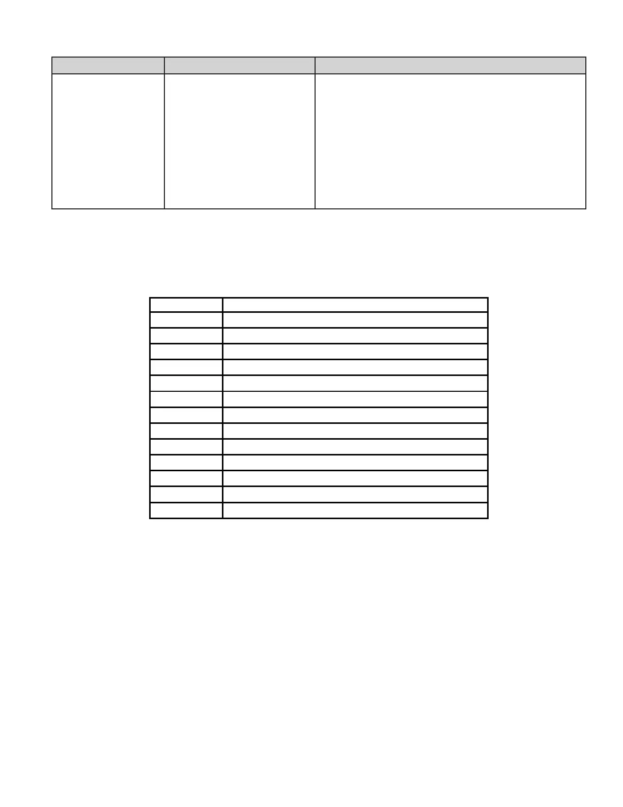
Problem Possible Cause Corrective Action
Pump runs without ow. Impeller is loose
Air in suction line or pump
Clogged or restricted plumbing
Ensure fan at the rear of pump is spinning. If so, disassemble pump
(Pump Disassembly, page 15) and ensure impeller is correctly installed.
1. Inspect suction line plumbing and valve(s) for damage or loose
connections.
2. Ensure the strainer pot lid is sealing properly. Verify lid o-ring is in
place.
3. Ensure proper pool water level and water is available to the skimmer.
1. Inspect for and clear any blockage in strainer pot or suction line.
2. Inspect for blockage in discharge piping including partially closed valve
or dirty pool lter.
Troubleshooting Chart (cont.)
Alarms and Fault Codes
If an alarm is triggered the drive will display a fault code text and the pump will stop running. Disconnect power to the pump
and wait until the keypad LEDs have all turned o, then reconnect power. If the error continues to appear after power is
reconnected, proper troubleshooting will be required. Use the error description table below to begin troubleshooting.
21
Communication link between HMI and motor control has been lost
1A
Power Module over current detected
17
Phase Current Offset out of range
16
Phase Current Imbalance detected
0F
Absolute AC under voltage detected
02
Absolute Phase current limit exceeded
08
Absolute Diode Bridge temperature limit exceeded
04
Absolute Power Module temperature limit exceeded
06
Absolute Power Factor Correction (PFC) temperature limit exceeded
09
DC bus over voltage detected
0A
DC bus under voltage detected
19
Motor start failure
0b
AC Voltage maximum exceeded
21 – Communication Link between the HMI and Motor Control has been lost: Remove the top cover from the drive
and inspect the jacketed wire on the backside of the keypad. Ensure that the 5-pin connector is properly plugged into the
socket and that there is no damage to the cable.
02 – Power Module Over Current Detected: If this error displays multiple times, then there may be a problem with the
pump’s rotating assembly. Disassemble the pump (see Pump Disassembly on page 15) and inspect the impeller and
shaft seal for problems.
0F – Absolute AC Under Voltage Detected: Indicates that the supply voltage has dropped below the operating range of
99v. This could be caused by normal voltage variation and will clear itself. Otherwise there could be excess voltage drops
caused by improper installation or improper supply voltage.
19 – Motor Start Failure: Could indicate a locked rotor. Verify the fan at the rear of the motor is free of debris. Attempt to
break up impeller blockages by rotating the motor shaft through the fan cover using a hex-key. If this does not work the
pump may need to be disassembled (see Pump Disassembly on page 15).
0b – AC Voltage Maximum Exceeded: Indicates that the supply voltage is exceeding the operating range of 251v.
1A,17,16, 02, 08, 04, 06, 09, 0A – Internal Errors: These errors can occur based on operating conditions and the required
self-diagnostic safety software. If they do not clear after multiple restart attempts the drive should undergo a hard power
cycle. Disconnect power at the circuit breaker long enough for the keypad LEDs to turn o. If the error continues to appear
after power is reconnected, the drive may need service.
 Loading...