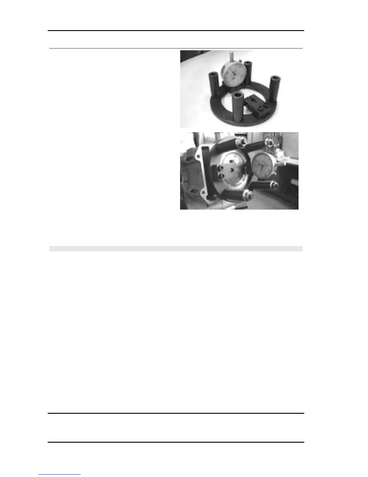
- Using an abutment plane, reset the dial gauge
with a preload of a few millimetres.
- Finally fix the dial gauge.
- Check the perfect sliding of the feeler pin.
- Install the tool on the cylinder without changing
the dial gauge position.
- Lock the tool using the original head fixing nuts.
- Rotate the crankshaft up to the TDC (the inver-
sion point of the dial gauge rotation)
- Measure the deviation from the reset value.
- Identify the thickness of the cylinder base gasket to be used for reassembly by the table below. Cor-
rectly identify the cylinder base gasket thickness to keep the correct compression ratio.
- Remove the special tool and the cylinder.
N.B.
IF DEVIATIONS (OR RECESSES OR PROJECTIONS) CLOSE TO THE CHANGE OF CATEGORY
ARE MEASURED, REPEAT THE MEASUREMENT AT THE OPPOSED SIDE. TO DO SO, REPEAT
THE TOOL INSTALLATION BY INVERTING ITS POSITION.
Characteristic
Recess / Projection measured 1
- 0.185 - - 0.10
Gasket thickness 1
0.4 ± 0.05
Recess / Projection measured 2
- 0.10 - + 0.10
Gasket thickness 2
0.6 ± 0.05
Recess / Projection measured 3
+ 0.10 ÷ + 0.185
Gasket thickness 3
0.8 ± 0.05
Engine Beverly 500 i.e.
ENG - 116

 Loading...