YES go to 18
18
Electric characteristic
Measured value =
0 V
Repeat the sensor and circuit earth insulation
check.
YES go to 19 NO go to 20
19 - Check the control unit connector.
Check the control unit power supply.
Replace the control unit, if necessary.
20 - Repair or replace the cable harness.
21 - Start the engine and check that voltage de-
creases gradually according to the temperature
increase as per table.
YES go to 22 NO go to 23
22 - The temperature signal is conforming.
23 - Replace the temperature sensor.
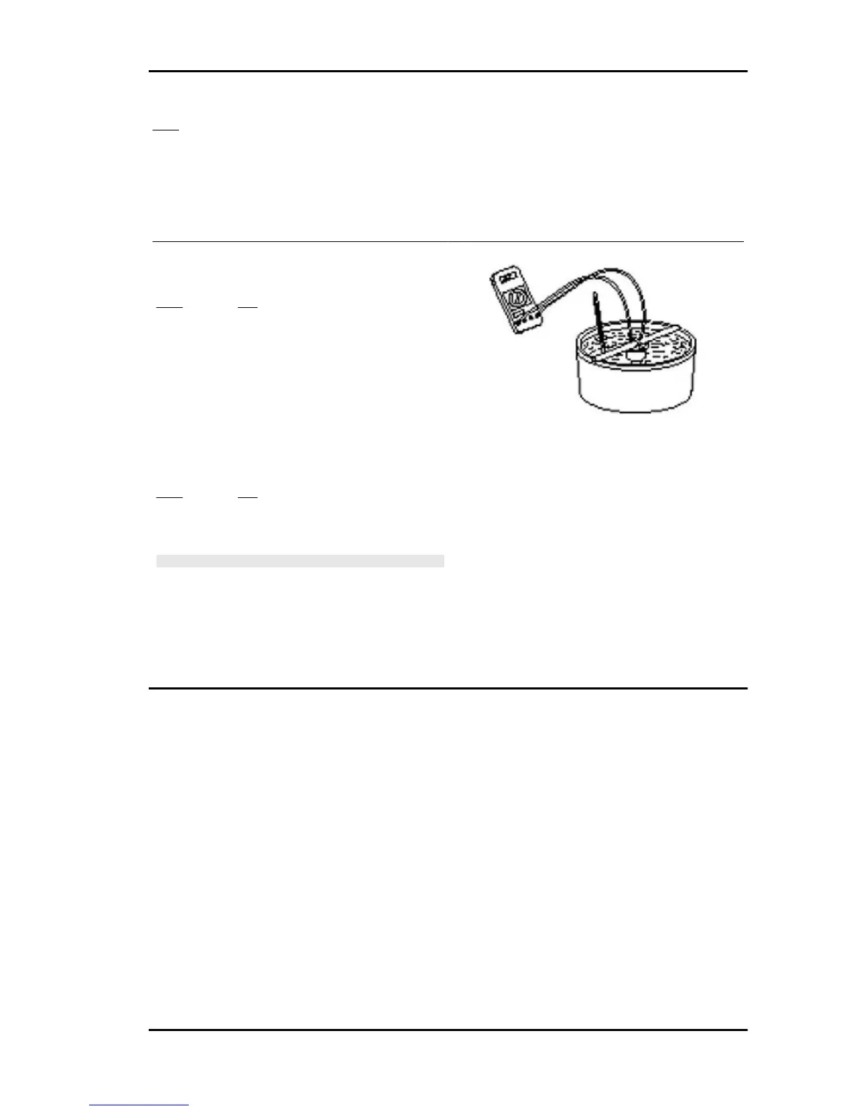
N.B.
FOR A MORE ACCURATE CHECK OF THE SENSOR, RE-
MOVE IT FROM THE ENGINE AND CHECK ITS RESIST-
ANCE AT CONTROLLED TEMPERATURE.
USING A SUITABLE CONTAINER, IMMERSE THE METAL
PORTION OF THE SENSOR IN WATER, HEAT GRADUAL-
LY AND READ THE TEMPERATURE AND RESISTANCE
VALUES.
CHECK THE MATCHING AS PER TABLE
Intake air temperature sensor
Electric characteristic
TERMINALS: 18 - 22
CONDITIONS: Intake air temperature 20°
STANDARD: With connected sensor: 3750 ± 200 Ω
Beverly 500 i.e. Injection
INJEC - 241
 Loading...