CIRCUIT LAYOUT
Specification
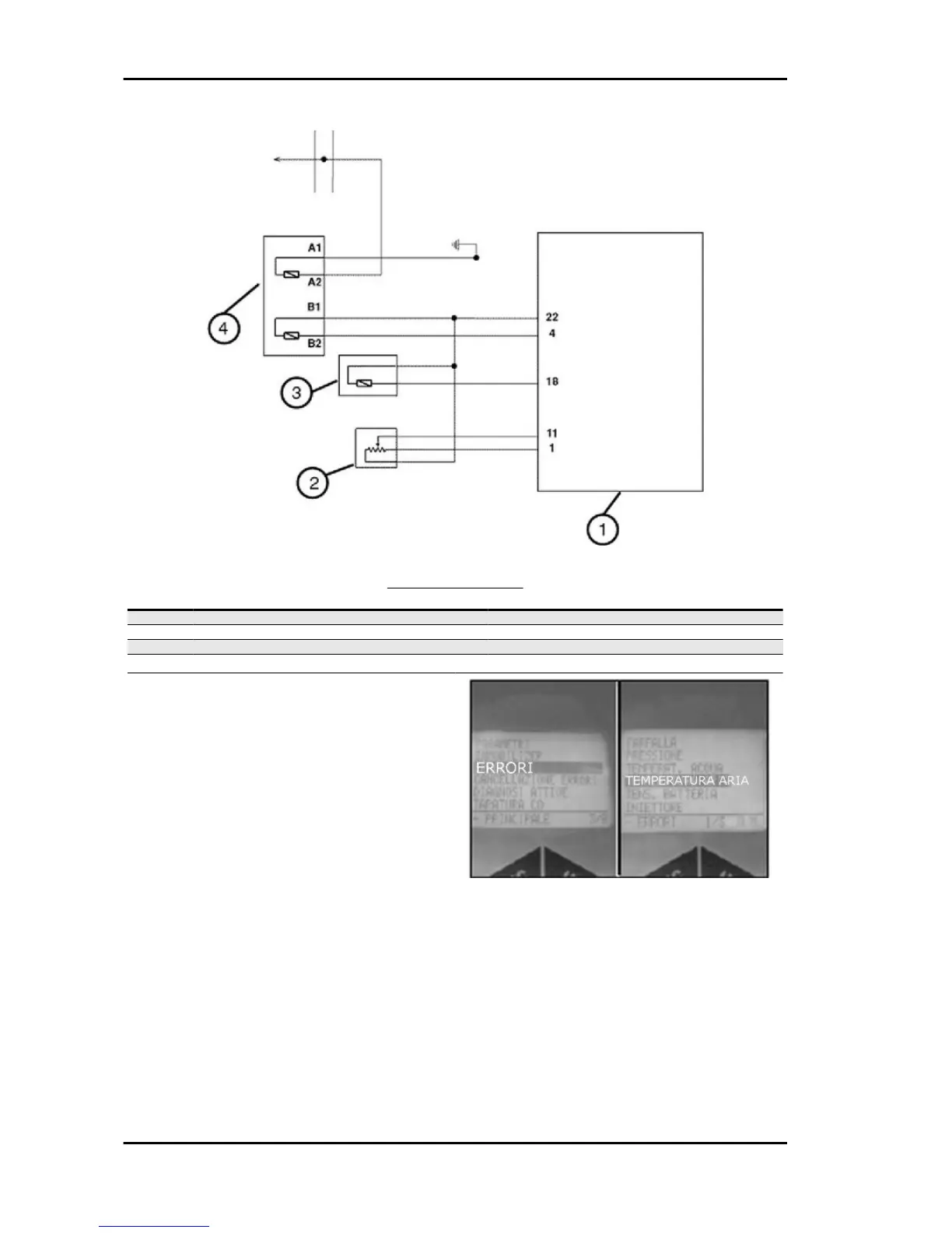
Desc./Quantity
1 Electronic control unit
2 Valve position sensor
3 Air temperature sensor
4 Fluid temperature sensor
The sucked air temperature sensor is installed in
the bottom side of the throttle body on the filter box
side.
The sensor is an NTC and has the same functional
layout as the coolant temperature sensor.
This signal is used to optimise the engine perform-
ance. Anyway, this data is less important than the
coolant temperature signal.
A failure of this circuit causes the control unit to
turn on the injection warning light and activate the
safety control, thereby ensuring the engine oper-
ation.
To check the sensor and related circuit, proceed
as follows:
1 - Connect the diagnostic tester.
Select the function "ERRORS" in the menu.
Injection Beverly 500 i.e.
INJEC - 242

 Loading...