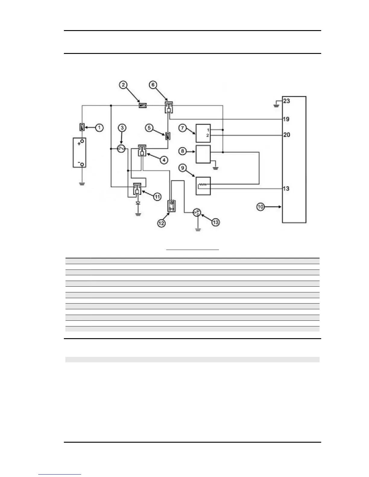
Circuit diagram
CIRCUIT LAYOUT
Specification
Desc./Quantity
1 Fuse 30A
2 Fuse 10 A
3 Switch
4 Engine stop remote control switch
5 Fuse 5A
6 Control unit remote control switch
7 HV coil
8 Fuel pump
9 Injector
10 Electronic injection control unit
11 Main remote control switch
12 Engine stop switch
13 Stand switch
Removing the injector
N.B.
ONLY REMOVE THE INJECTOR FROM THE MANIFOLD IN THE EVENT OF A PROVEN DEFECT.
OPERATING TEST OF THE INJECTOR MUST BE PERFORMED WITH THE INJECTOR INSTALLED
ON THE MANIFOLD (SEE "INJECTION").
Beverly 500 i.e. Injection
INJEC - 191
 Loading...