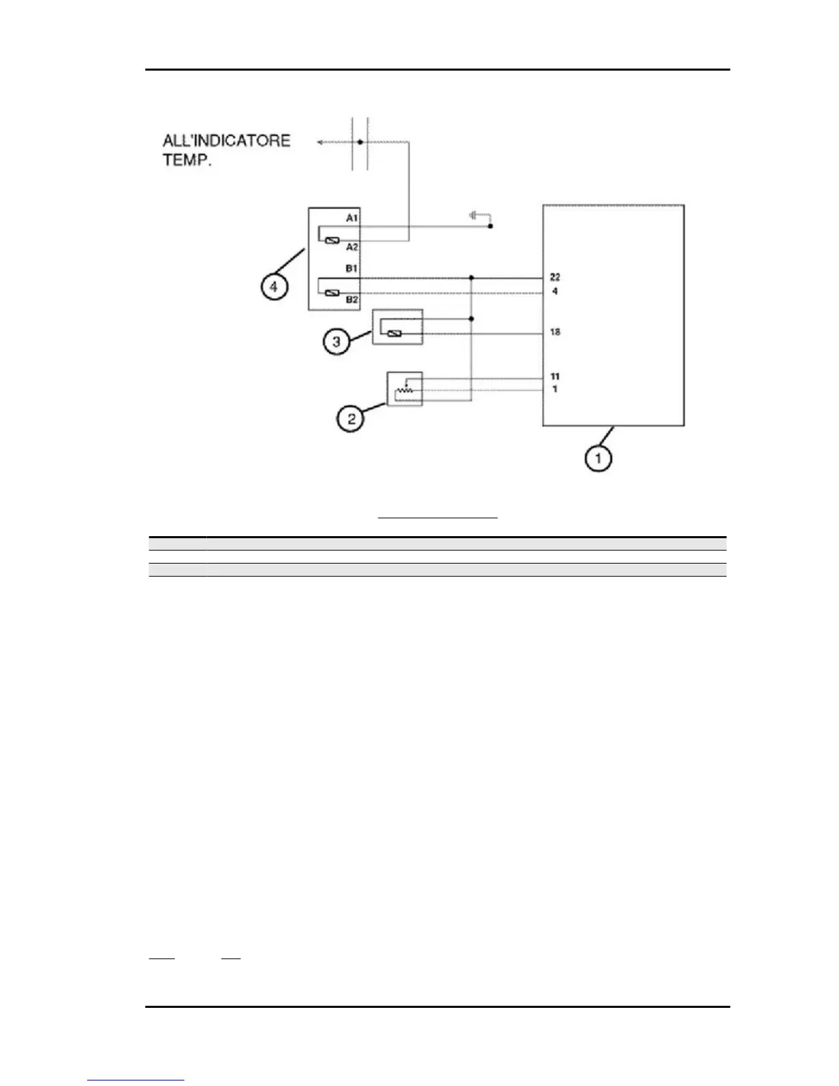
CIRCUIT LAYOUT
Specification
Desc./Quantity
1 Electronic control unit
2 Valve position sensor
3 Air temperature sensor
4 Fluid temperature sensor
The coolant temperature sensor is installed on the engine head and provides the indications for the
digital instrument and for the injection.
It is realised with two electrically different sections.
The injection section is realised with an NTC sensor connected to a 5V powered circuit. The resistance
variation causes a variation of the circuit voltage. Such voltage is combined with a temperature value.
By this value, the control unit can manage the engine operation, optimising it for all temperatures.
A failure of this circuit causes the switching on of the injection telltale light and the tripping of the safeties
(among which the electric fan continuous start). In these conditions, the engine works, even though not
in an optimum way, always safeguarding the catalytic converter integrity.
A false temperature value that falls within the range of possible temperatures is a failure very difficult
to manage. This can cause a failure of the safeties and an improper management of the ignition. Such
failure is more easily detected upon the engine start-up.
To check the sensor and related circuit, proceed as follows:
1 - Connect the injection diagnostic tester and select the menu on the "errors" function.
Check whether faults have been recorded regarding the coolant temperature sensor.
YES go to 3 NO go to 2
Specific tooling
Beverly 500 i.e. Injection
INJEC - 237

 Loading...