Fitting clearance (Cylindrin/Pison)
Standard coupling clearance A 0.9 - 0.005 -0.030mm B 1.5 - 0.005 -0.03mm Maximum permissible
clearance after use C 0.9 + 0.03 +0.01mm D 2 + 0.05 +0.02mm Standard coupling clearance </>
1.2 - 0.005 mm </> </> Maximum permissible clearance after use </> 1.25 + 0.03 mm </> </>
Standard coupling clearance </> 2.5 - 0.005 mm </> </> Maximum permissible clearance after
use </> 2.5 + 0.03 mm </> </>
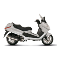
Inspecting the piston rings
- Alternately insert the three sealing rings into the
cylinder, in the area where it retains its original di-
ameter. Using the piston, insert the rings perpen-
dicularly to the cylinder axis.
- Measure the opening (see figure) of the sealing
rings using a feeler gauge.
- If higher values than those prescribed are meas-
ured, replace the linings.
N.B.
BEFORE REPLACING ONLY THE PISTON RINGS, ENSURE THAT THE CLEARANCE BETWEEN
THE PISTON RINGS AND THE PISTON RING GROOVES, AND BETWEEN THE PISTON AND THE
CYLINDER, IS AS SPECIFIED. IN ANY CASE, NEW PISTON RINGS USED IN COMBINATION WITH
A USED CYLINDER MAY HAVE DIFFERENT BEDDING CONDITIONS THAN THE STANDARD.
Fitting clearance (Cylindrin/Pison)
Compression ring 0.15 ÷ 0.35 mm Max. value. 0.5 mm </> Oil scraper ring 0.25 ÷ 0.50 mm Max.
value. 0.65 mm </> Oil scraper ring 0.25 ÷ 0.50 mm Max. value. 0.65 mm </>
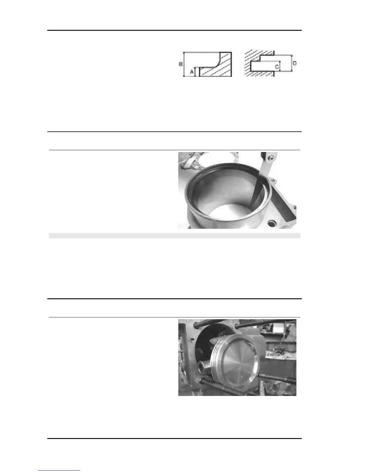
Removing the piston
- Install piston and wrist pin onto the connecting
rod, aligning the piston arrow the arrow facing to-
wards the exhaust.
Engine X8 400 Euro 3
ENG - 140
 Loading...