72-910-16 Rev. N
Page 36 of 43
11. MAINTENANCE
The only recommended maintenance required on your controller is periodic
inspection of the conductivity sensor every 6 months. It is recommended that you
establish a regular maintenance schedule designed to meet the needs of your
particular application. All other service should be performed by factory authorized
personnel only. Modifications to or tampering with the circuit level components
makes all warranties, written or implied, and/or manufacturer’s responsibility for this
controller, null and void.
DISCONNECT POWER BEFORE OPENING THE UNIT TO ACCESS FUSES. MAKE SURE
THAT REPLACEMENT FUSES ARE OF SAME TYPE TO MAINTAIN SAFTEY APPROVALS.
5A, IEC 60127-2 · 250 VAC · Time-Lag T
1A, 2AG, Time Lag, 250VAC
12. SPECIFICATIONS
NEMA 4X/ Designed to meet IP65
6.4" x 3.2" x 3.2" (163 x 82 x 82mm)
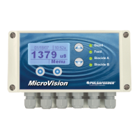
LCD 0 - 9,999 µS/cm range 1µS/cm resolution
Maximum relay output current
120 VAC:
5 A Resistive/General use
4LRA/4FLA,1/10HP (motors)
220 VAC:
5 A Resistive/General use
Not rated for motors
All fuses are UL, CSA recognized or listed.
F3 is not serviceable in the field.
 Loading...