28
DELTABELL-WE
External sounder
Technical specification
Installation Steps:
Step 1
Step 2
Step 3
Tamper
levelling
screw
AC/DC
BATTERY
SOUNDER
TAMPER
LEARN
BAT
+
-
LED3 LED2 LED1
Comfort LED
Enable/Disable
link
Learn button
Optional
auxillary 12
volt PSU input
Battery
Sounder
Tamper
Red LED
Blue LED
Green LED
Strobe
Comfort LEDs
The batteries supplied have been
chosen to provide long service life
whilst, for safety reasons, having
limited output current.
Replace only with approved batteries.
To prevent possible damage to
components, any static charge on your
body needs to be eliminated before
touching the inside of the unit. This can
be accomplished by touching some
grounded/earthed metallic conductor
such as a radiator/pipework
immediately before replacing batteries.
Battery
Tamper switch
Battery CR3 3.0 volt
11000MAh
Lithium battery
Strobe duration 10mS
Strobe Frequency 1Hz
Sound pressure level 101dBA
Dimensions 290 x 285 x 50 mm
Reverse polarity protected
Tamper
levelling
screw
AC/DC
BATTERY
SOUNDER
TAMPER
LEARN
BAT
+
-
LED3 LED2 LED1
Comfort LED
Enable/Disable
link
Learn button
Optional
auxillary 12
volt PSU input
Battery
Sounder
Tamper
Red LED
Blue LED
Green LED
Strobe
Comfort LEDs
The batteries supplied have been
chosen to provide long service life
whilst, for safety reasons, having
limited output current.
Replace only with approved batteries.
To prevent possible damage to
components, any static charge on your
body needs to be eliminated before
touching the inside of the unit. This can
be accomplished by touching some
grounded/earthed metallic conductor
such as a radiator/pipework
immediately before replacing batteries.
Battery
Tamper switch
Battery CR3 3.0 volt
11000MAh
Lithium battery
Strobe duration 10mS
Strobe Frequency 1Hz
Sound pressure level 101dBA
Dimensions 290 x 285 x 50 mm
Reverse polarity protected
Tamper
levelling
screw
AC/DC
BATTERY
SOUNDER
TAMPER
LEARN
BAT
+
-
LED3 LED2 LED1
Comfort LED
Enable/Disable
link
Learn button
Optional
auxillary 12
volt PSU input
Battery
Sounder
Tamper
Red LED
Blue LED
Green LED
Strobe
Comfort LEDs
The batteries supplied have been
chosen to provide long service life
whilst, for safety reasons, having
limited output current.
Replace only with approved batteries.
To prevent possible damage to
components, any static charge on your
body needs to be eliminated before
touching the inside of the unit. This can
be accomplished by touching some
grounded/earthed metallic conductor
such as a radiator/pipework
immediately before replacing batteries.
Battery
Tamper switch
Battery CR3 3.0 volt
11000MAh
Lithium battery
Strobe duration 10mS
Strobe Frequency 1Hz
Sound pressure level 101dBA
Dimensions 290 x 285 x 50 mm
Reverse polarity protected
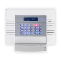
Slide the PCB module upwards. The sprung back-tamper arm can be
retracted to allow removal. This must be done in order to install the
revolving guides - see step 3.
Place the base on a flat surface and ensure it is vertical using the Spirit
level that is already installed. Drill and plug in each of the fixing locations.
The revolving guides will correct any misalignment. If the Deltabell WE
must be mounted on an uneven surface, it is recommended that a tamper
levelling screw is used to ensure correct back-tamper operation. See step 2.
Mounting the Deltabell WE on an uneven surface may cause false
triggering, through incorrect operation of the back-tamper.
A POZI number 2 screw driver is recommended for adjusting back tamper
screw.
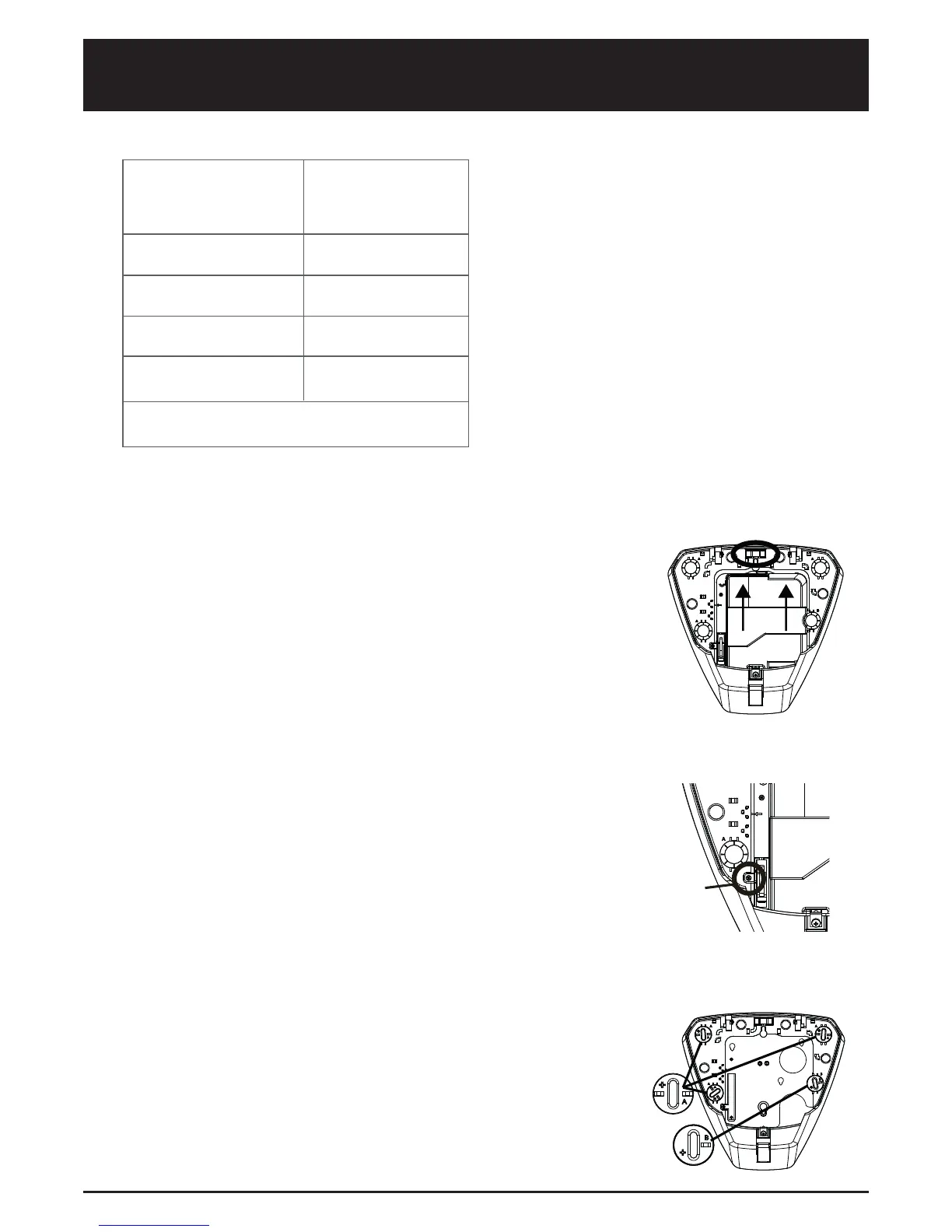
Insert the guides in as shown. Make sure that the guides ‘B’ is aligned with
the tabs to the right (this is so the PCB module slides in)
Turn each guide until they line up with the drilled holes, while referencing
the spirit level for the correct alignment and fix the base firmly to the wall.
Please note, if the Deltabell WE is installed on an uneven surface, it is
recommended that you do not tighten up the wall screws until after the
module is installed (step 4).

 Loading...