LTE Standard Module Series
3.2.2.1. USB Application with USB Suspend/Resume and RI Function
If the host supports USB Suspend/Resume, but does not support remote wakeup function, the MAIN_RI
signal is needed to wake up the host.
There are three preconditions to let the module enter sleep mode.
⚫ Execute AT+QSCLK=1 to enable the sleep mode.
⚫ Ensure the MAIN_DTR is held at high level or keep it open.
⚫ The host’s USB bus, which is connected with the module’s USB interface, enters Suspend state.
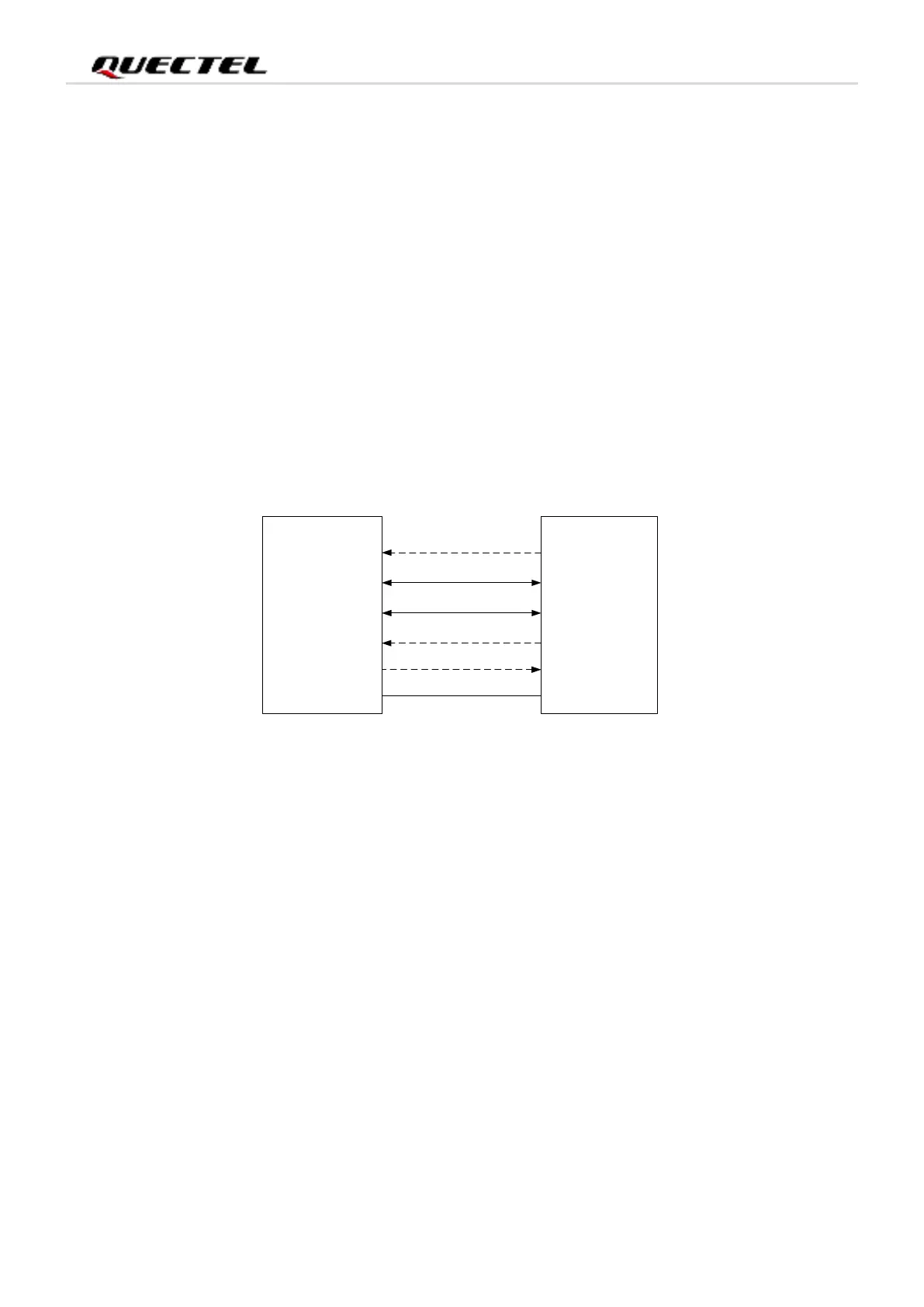
The following figure shows the connection between the module and the host.
USB_VBUS
USB_DP
USB_DM
AP_READY
VDD
USB_DP
USB_DM
GPIO
Module Host
GND
GND
MAIN_RI
EINT
Figure 4: Sleep Mode Application with MAIN_RI
⚫ Sending data to EC200A series through USB will wake up the module.
⚫ When EC200A series has a URC to report, the URC will trigger the behavior of MAIN_RI pin. Please
refer to Chapter 4.9 for details about MAIN_RI behavior.
3.2.2.2. USB Application without USB Suspend Function
If the host does not support USB Suspend function, please disconnect USB_VBUS with additional control
circuit to let the module enter into sleep mode.
⚫ Execute AT+QSCLK=1 command to enable the sleep mode.
⚫ Ensure the MAIN_DTR is held at high level or keep it open.
⚫ Disconnect USB_VBUS.