EasyManuals Logo
Home>Quectel>Control Unit>EC200A Series

Quectel EC200A Series User Manual

Quectel EC200A Series
97 pages
To Next Page IconTo Next Page
To Previous Page IconTo Previous Page
Page #61 background imageLoading...
Page #61 background image
LTE Standard Module Series
5.1.4. Reference Design
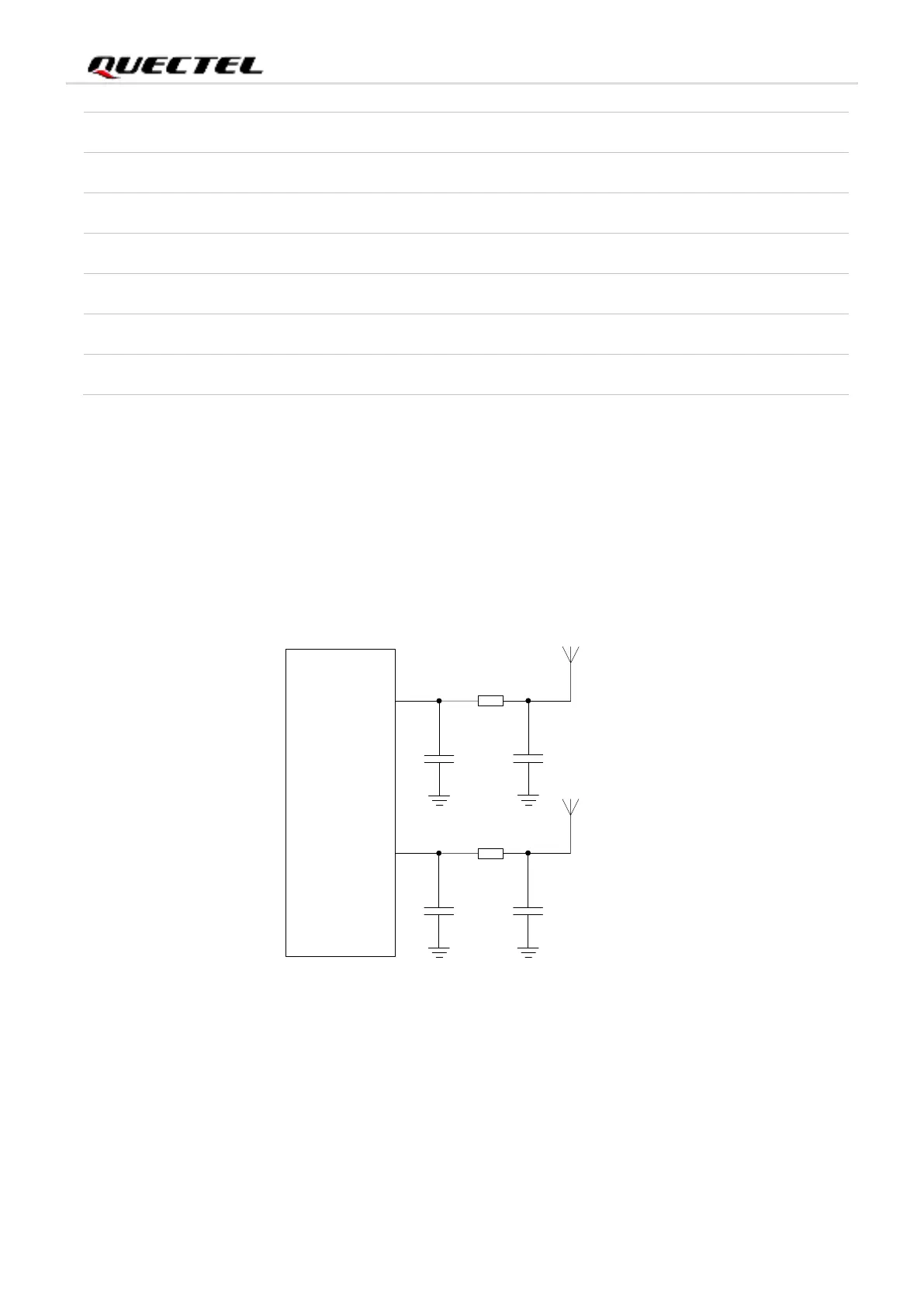
The module provides two RF antenna interfaces for antenna connection.
It is recommended to reserve a π-type matching circuit for better RF performance, and the π-type
matching components (C1, R1, C2 and C3, R2, C4) should be placed as close to the antenna as possible.
The capacitors are not mounted by default.
ANT_MAIN
R1 0 R
C1
Module
Main
antenna
NM
C2
NM
R2 0 R
C3
Diversity
antenna
NM
C4
NM
ANT_DRX
Figure 28: Reference Circuit for RF Antenna Interfaces
LTE-FDD B7
-94.4
-95.8
-98
-94.3 dBm
LTE-FDD B8
-96.7
-98.9
-100.1
-93.3 dBm
LTE-FDD B20
-98.1
-99.3
-101.4
-93.3 dBm
LTE-FDD B28
-98.9
-99.5
-102.6
-94.8 dBm
LTE-TDD B38
-96.5
-95.2
-99.3
-96.3 dBm
LTE-TDD B40
-97.3
-97.3
-100.5
-96.3 dBm
LTE-TDD B41
-94.9
-95.1
-97.8
-94.3 dBm

Table of Contents

Questions and Answers:

Question and Answer IconNeed help?

Do you have a question about the Quectel EC200A Series and is the answer not in the manual?

Quectel EC200A Series Specifications

General IconGeneral
BrandQuectel
ModelEC200A Series
CategoryControl Unit
LanguageEnglish

Related product manuals