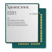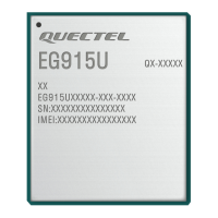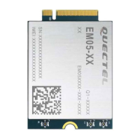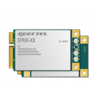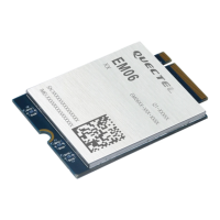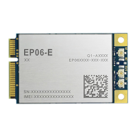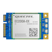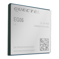

Do you have a question about the Quectel EG06 Series and is the answer not in the manual?
| Module Type | LTE Cat 6 Module |
|---|---|
| Category | Control Unit |
| LTE Category | Cat 6 |
| Max Download Speed | 300 Mbps |
| Max Upload Speed | 50 Mbps |
| Operating Temperature | -40°C to +85°C |
| Storage Temperature | -40°C to +90°C |
| Power Consumption | TBD |
| SIM Interface | 1.8V/3.0V |
| GNSS | GPS/GLONASS/BeiDou/Galileo/QZSS |
| Power Supply | 3.3V |
| Protocols | TCP/IP, UDP, HTTP, FTP |
| Certifications | CE, FCC, GCF, PTCRB |
| Interface | USB 2.0, UART |
| Network Support | LTE, WCDMA, GSM |
| Form Factor | M.2 |
| Dimensions | 30.0 × 42.0 × 2.3 mm |
Essential safety precautions for operating the EG06 module during all phases of use.
Overview of the EG06 series modules and their supported networks.
Detailed features of the EG06 module, including power, LTE, UMTS, and interfaces.
Block diagram illustrating the EG06 module's major functional parts and interfaces.
Information on the EG06 evaluation board (EVB) and peripherals for application development.
Description of EG06 LGA pads and the sub-interfaces covered in the document.
Detailed pin assignment diagram for the EG06 module, showing pin names and numbers.
Definition and description of EG06 module pins, including DC characteristics.
Summary of various operating modes of the EG06 module, such as Idle, Sleep, and Airplane mode.
Procedures and applications for enabling sleep mode on the EG06 module via UART or USB.
Details on EG06 power supply pins, voltage requirements, and reference designs for stable power.
Procedures for turning the EG06 module on and off using the PWRKEY pin or AT commands.
Method for resetting the EG06 module using the RESET_N pin, including circuit and timing.
(U)SIM interface circuitry, pin definitions, and reference designs for 8-pin and 6-pin connectors.
Definition and reference circuit for the EG06 module's USB interface, supporting USB 3.0/2.0.
Description of main, debug, and BT UART interfaces, including pin definitions and logic levels.
PCM and I2C interfaces for audio communication, including modes, timing, and pin definitions.
Definition and characteristics of the EG06 module's two Analog-to-Digital Converter (ADC) interfaces.
Network status indication pins (NET_MODE, NET_STATUS) and their working states.
Definition of the STATUS pin as a module operation status indicator.
Configuration and default behavior of the RI (Ring Indicator) pin for URC notifications.
Features and pin definition of the EG06 module's PCI Express interface.
Control interface for WLAN design, including pin definitions for coexistence and control signals.
SD card interface supporting SD 3.0 protocol, including pin definitions and reference circuits.
SPI interface details, including pin definitions, timing parameters, and reference circuit with level translator.
USB_BOOT interface for entering emergency download mode and firmware upgrade.
Description of the EG06 GNSS receiver solution and its supported satellite systems.
GNSS performance metrics including sensitivity, TTFF, and accuracy.
Layout guidelines for the EG06 GNSS antenna and related circuits to ensure performance.
Pin definition and operating frequencies for the main and Rx-diversity antenna interfaces.
Pin definition and frequency specifications for the GNSS antenna interface.
Requirements for main, Rx-diversity, and GNSS antennas, and recommended RF connectors.
Absolute maximum ratings for power supply and voltage on EG06 module pins.
Power supply ratings for VBAT and USB_VBUS, including typical and maximum values.
Operating and storage temperature ranges for the EG06 module, including extended ranges.
Typical current consumption of the EG06 module in various states like sleep, idle, and data transfer.
RF output power specifications for WCDMA, LTE-FDD, and LTE-TDD bands.
Conducted RF receiving sensitivity for EG06 module across various frequency bands and configurations.
Electrostatic discharge characteristics of the EG06 module and handling precautions.
Principles for thermal management, heatsink designs, and placement to ensure optimal module performance.
Mechanical dimensions of the EG06 module, including top, side, and overall size.
Recommended PCB footprint for the EG06 module, including pad layout and dimensions.
Design effect drawings showing the top and bottom views of the EG06 module.
Storage conditions, shelf life, and handling requirements for EG06 modules after opening the vacuum seal.
Guidelines for manufacturing and soldering the EG06 module, including reflow soldering thermal profile.
Details on EG06 module packaging, including tape and reel carrier specifications.
FCC compliance statement and regulations for the EG06 module, including interference guidelines.
RF exposure compliance information and minimum human proximity requirements for the EG06 module.
ISED (Canada) notice regarding device compliance with license-exempt RSS standards.
ISED radiation exposure limits and human proximity requirements for the EG06 module.
Guidance for end-user manuals regarding antenna separation and FCC compliance for the EG06 module.
Requirements for labeling the end product containing the EG06 module with FCC and ISED information.


