GSM/GPRS/GNSS Module Series
MC60 Series Hardware Design
MC60_Series_Hardware_Design Confidential / Released 61 / 114
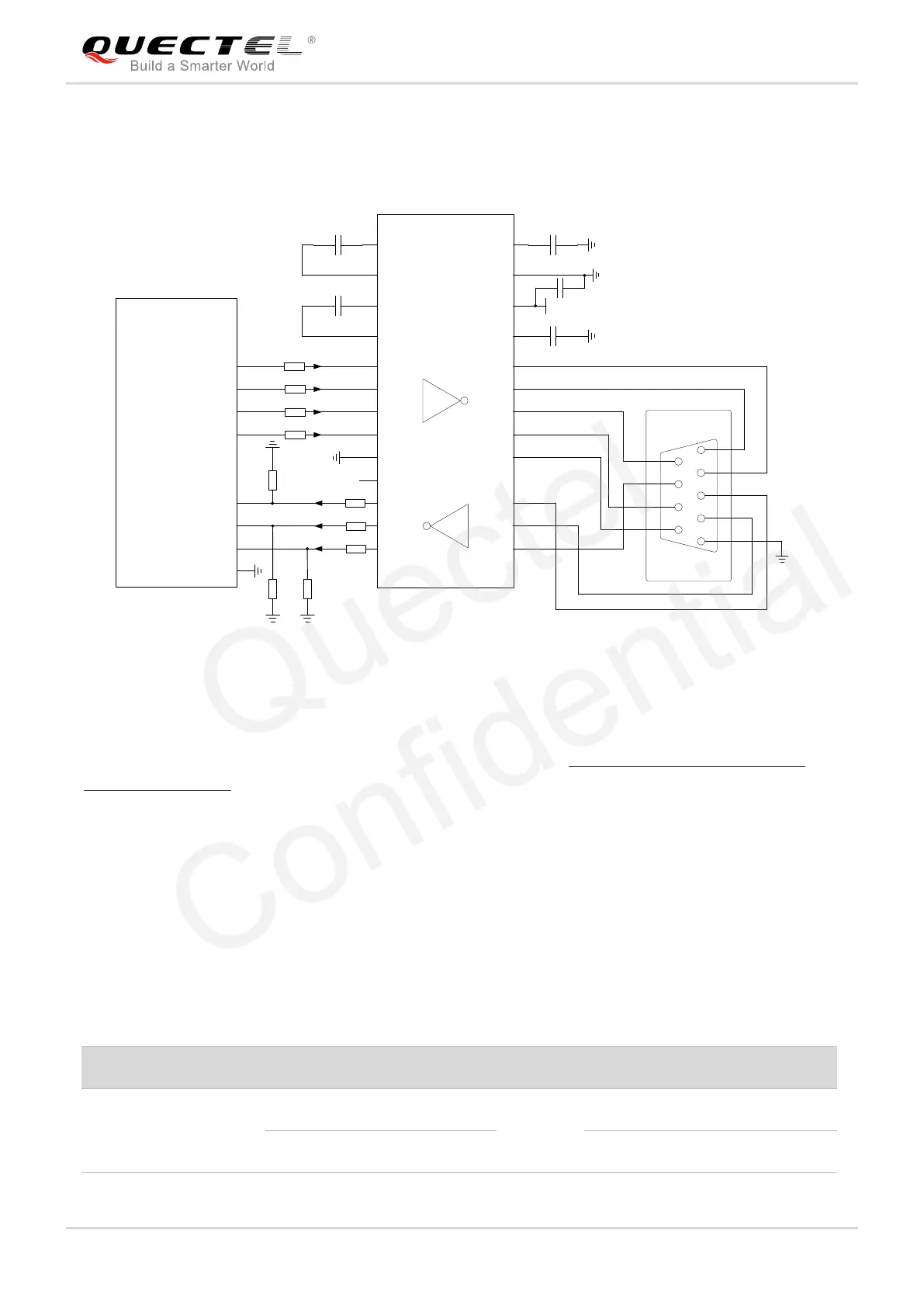
The following figure shows a sketch map between the module and the standard RS-232 interface. As the
electrical level of module is 2.8V, a RS-232 level shifter must be used. Note that customers should assure
the I/O voltage of level shifter which connects to module is 2.8V.
TXD
RXD
RTS
CTS
DTR
RI
DCD
Module
GND
C1+
C1-
C2+
C2-
V+
VCC
GND
V-
3.3V
T1IN
T2IN
T3IN
T4IN
R1IN
R2IN
R3IN
R1OUT
R2OUT
R3OUT
T1OUT
T2OUT
T5OUT
T3OUT
T4OUT
T5IN
GND
GND
/R1OUT
1
2
3
4
5
6
7
8
9
GND
To PC Serial Port
GND
1K
1K
1K
1K
1K
5.6K5.6K
1K
1K
5.6K
RS-232 Level Shifter
Figure 31: Sketch Map for RS-232 Interface Match
Please visit vendors’ websites to select a suitable IC, such as: http://www.maximintegrated.com and
http://www.exar.com.
3.10. Audio Interfaces
The module provides one analog input channel and two analog output channels.
Table 17: Pin Definition of Audio Interface
Microphone positive input
Microphone negative input

 Loading...


