GSM/GPRS/GNSS Module Series
MC60 Series Hardware Design
MC60_Series_Hardware_Design Confidential / Released 87 / 114
In All-in-one solution, please note that the power supply of GNSS_VCC is controlled by the GSM part via
AT command.
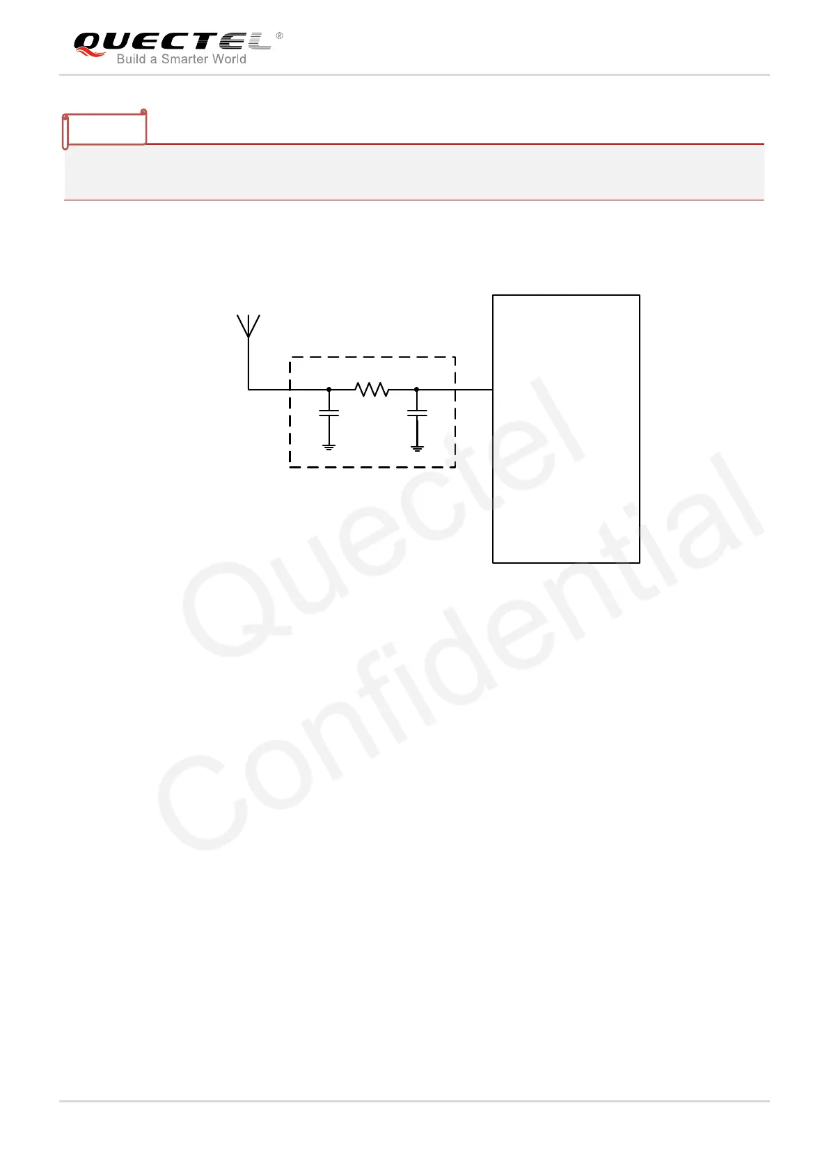
4.2.3. Passive Antenna
Module
Passive Antenna
GNSS_ANT
C1 NM
C2 NM
R1
П matching circuit
0R
Figure 52: Reference Design with Passive Antenna
The above figure is a typical reference design with passive antenna.
C1, R1 and C2 are reserved matching circuit for antenna impedance modification. C1 and C2 are not
mounted by default; R1 is 0Ω. Impedance of RF trace should be controlled as 50Ω and the trace length
should be kept as short as possible.

 Loading...


