GSM/GPRS/GNSS Module Series
MC60 Series Hardware Design
MC60_Series_Hardware_Design Confidential / Released 72 / 114
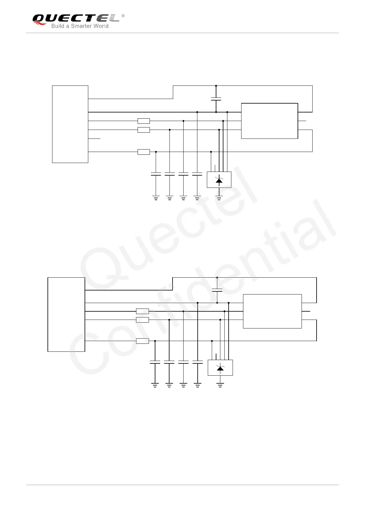
If (U)SIM1 card insertion detection function is not used, keep pin SIM1_PRESENCE unconnected. A
reference circuit for (U)SIM1 card interface with a 6-pin (U)SIM card connector is illustrated in the following
figure.
Module
22R
22R
22R
100nF
GND
TVS
33pF 33pF 33pF
VCC
RST
CLK IO
VPP
GND
GND
33pF
(U)SIM Card Connector
SIM_GND
SIM1_VDD
SIM1_RST
SIM1_CLK
SIM1_PRESENCE
SIM1_DATA
Figure 41: Reference Circuit for (U)SIM1 Card Interface with a 6-Pin (U)SIM Card Connector
The following figure shows a reference design for (U)SIM2 card interface with a 6-pin (U)SIM card
connector.
Module
22R
22R
22R
100nF
GND
TVS
33pF 33pF 33pF
VCC
RST
CLK IO
VPP
GND
GND
33pF
(U)SIM Card Connector
SIM_GND
SIM2_VDD
SIM2_RST
SIM2_CLK
SIM2_DATA
Figure 42: Reference Circuit for (U)SIM2 Card Interface with a 6-Pin (U)SIM Card Connector
In order to enhance the reliability and availability of the (U)SIM card in applications, please follow the
criteria below in (U)SIM circuit design:
Keep layout of (U)SIM card as close to the module as possible. Keep the trace length as less than

 Loading...


