Raisecom
ISCOM2600 (B) Series Product Description
Raisecom Proprietary and Confidential
Copyright © Raisecom Technology Co., Ltd.
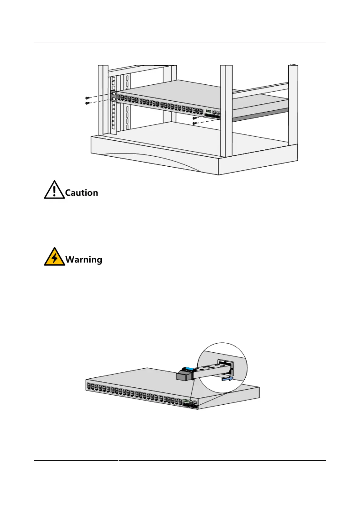
Figure 4-4 Installing the device horizontally in the rack
Do not lay heavy objects or coverings on the ISCOM2600 series switch.
4.1.3 Connecting cables
Connecting fiber
There is invisible laser which harms eyes inside the ISCOM2600 series switch. Do
not stare into the optical interface, fiber connector, or breakage of fiber directly.
Connect fiber as below:
Step 1 Remove the dustproof cover from the SFP optical interface and SFP optical module, and
insert the SFP optical module into the optical interface on the ISCOM2600 series switch, as
shown in Figure 4-5.
Figure 4-5 Inserting the SFP optical module
Step 2 Remove the dustproof cover from the LC/PC fiber, align the fiber with the SFP optical
interface, and insert the fiber slightly into the SFP optical interface, as shown in Figure 4-6.
 Loading...

