The Spectrum Application
R&S
®
FPC
113User Manual 1178.4130.02 ─ 07
"External Fall": the measurement starts when the trigger signal falls below
1.4 V (a TTL signal level).
You can connect the external trigger source to the corresponding BNC connec-
tor on the rear panel of the R&S FPC.
Note that the BNC connector has to be configured as a trigger input in the
instrument setup.
Tip: As long as the measurement hasn't started, the R&S FPC displays "Waiting
for Trigger" in the diagram area.
Defining a trigger delay
When you are using an external trigger, you can delay the start of the measurement
with respect to the trigger event. Thus, you can include time differences between the
trigger event and the measurement.
1. Press the "Sweep" key to open the sweep menu.
2. Select the "Trigger" menu item to open the trigger menu.
3. Select the "Trigger Delay" menu item.
The R&S FPC opens an input field to define the delay time.
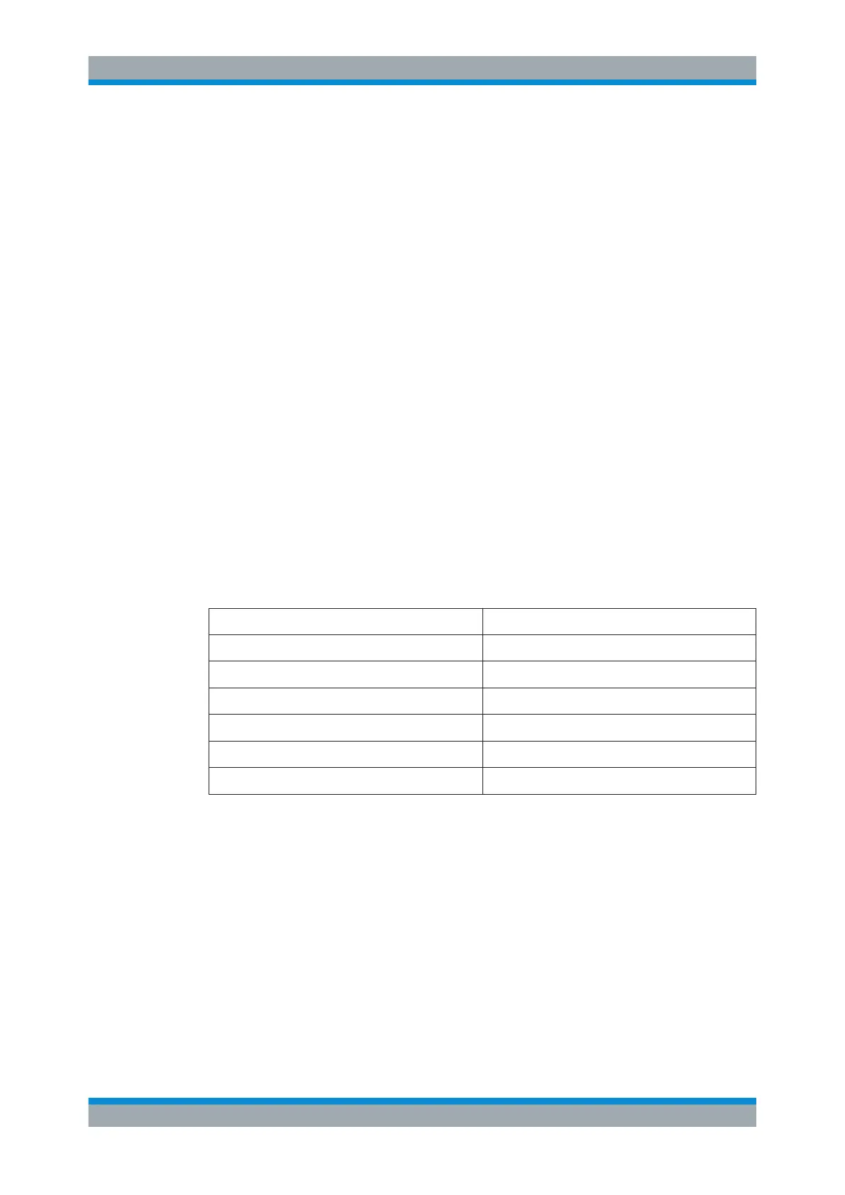
The range of the trigger delay is between 0 µs to 100 s. The resolution with which
you can select the delay time depends on the subrange of the delay time (see
Table 14-2).
Table 14-2: Trigger delay dependencies
Trigger delay Resolution
0 s to 1 ms 10 μs
1 ms to 10 ms 100 μs
10 ms to 100 ms 1 ms
100 ms to 1 s 10 ms
1 s to 10 s 100 ms
10 s to 100 s 1 s
14.8 Trace Configuration
Access: "Trace"
Access: "Setup" > "Config Overview" > "Analysis" (selected settings)
Remote commands to configure traces:
●
Chapter 19.12.7, "Traces", on page 265
The trace is the graphical representation of the measured spectrum. In the diagram, it
is represented by a colored graph. Depending on the trace configuration, the R&S FPC
evaluates and displays the measurement data differently.
Trace Configuration

 Loading...


