Operation
R&S
®
FPC
24User Manual 1178.4130.02 ─ 07
Softkeys can either perform a specific function or open an input field or dialog box.
Measurement settings bar
The measurement settings bar contains information about the current measurement
settings. A blue dot in front of a setting indicates that automatic selection for that set-
ting has been turned off.
Trace information
The trace information indicates the current trace configuration for each active trace
(trace color, trace number, trace mode and detector).
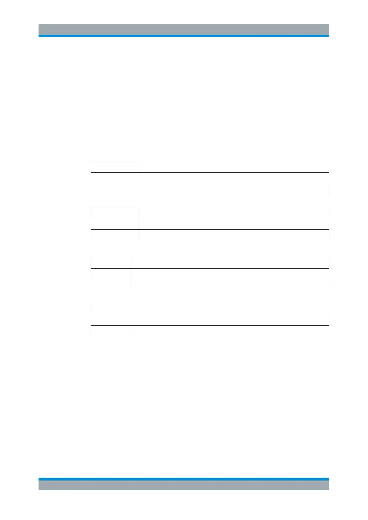
Table 5-1: Overview of trace modes
Abbreviation Detector
Clrw Clear / write trace mode
Max Max hold trace mode
Min Min hold trace mode
Avg Average trace mode
View View trace mode
No label Blank trace mode (trace is off)
Table 5-2: Overview of detectors
Abbreviation Detector
AP Auto peak detector
Pk Max peak detector
Mi Min peak detector
Rm RMS detector
Sa Sample detector
QP Quasipeak detector (receiver only)
Marker information
The marker information indicates the position of each active marker. If a marker func-
tion is active, it also shows the result for that marker function.
Limit line information
The limit line information indicates the characteristics of any active limit line (type of
limit line, name of limit line etc.), including the result of a limit check (pass or fail).
Diagram area
The diagram area contains the graphical representation of the measurement results.
Screen Layout

 Loading...


