CHAPTER
4
P/N 016-5032-114 Rev. A 23
CHAPTER 4
WHEEL ANGLE SENSOR (WAS)
INSTALLATION
1. Park the machine on a level surface, with the wheels pointing straight ahead.
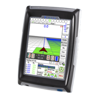
FIGURE 1. Rotary Sensor Assembly Alignment
2. Align the flat side of the shaft on the rotary sensor assembly (P/N 063-0181-013) so that it is parallel with the
cable exit point as shown in the figure above.
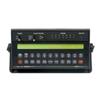
FIGURE 2. WAS Mounting Location
3. Remove the plastic cover from the top of the front right wheel to gain access to the steering cylinder area.
Flat Side
of Shaft
Cable Exit
Point

 Loading...