CHAPTER 5
36 Miller Nitro 5000 Series & New Holland Guardian F Series RS1™ HDU Guidance and Steering Installation Manual
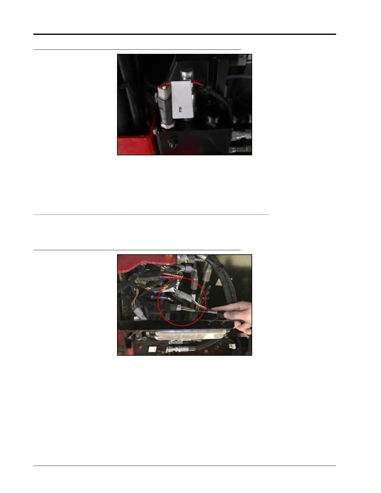
FIGURE 20. PSI Connection
4. Connect the PSI connector to the transducer (P/N 422-0000-086) installed in Port PS of the steering valve.
5. Connect the SPS connector to the cable of the installed rotary sensor (P/N 063-0181-013).
6. Connect the ENABLE connector to the installed foot switch, if applicable.
INSTALL THE FOUR-WHEEL STEER LOCKOUT HARNESS - FOUR-WHEEL
STEER MACHINES ONLY
FIGURE 21. Steering Lockout Cable Valve Connection
1. Disconnect the PVES connector of the valve harness (P/N 115-4001-140) from the steering valve.
2. Install the TO VALVE HARNESS connector of the steering lockout switch cable (P/N 115-4010-073) on the PVES
connector of the valve harness.
3. Connect the TO VALVE connector to the open port of the steering valve.

 Loading...