— English Fillcontrol Auto Make-up and degassing — 06.07.2016 - Rev. B
6.3.5 Fillcontrol Auto 2PS
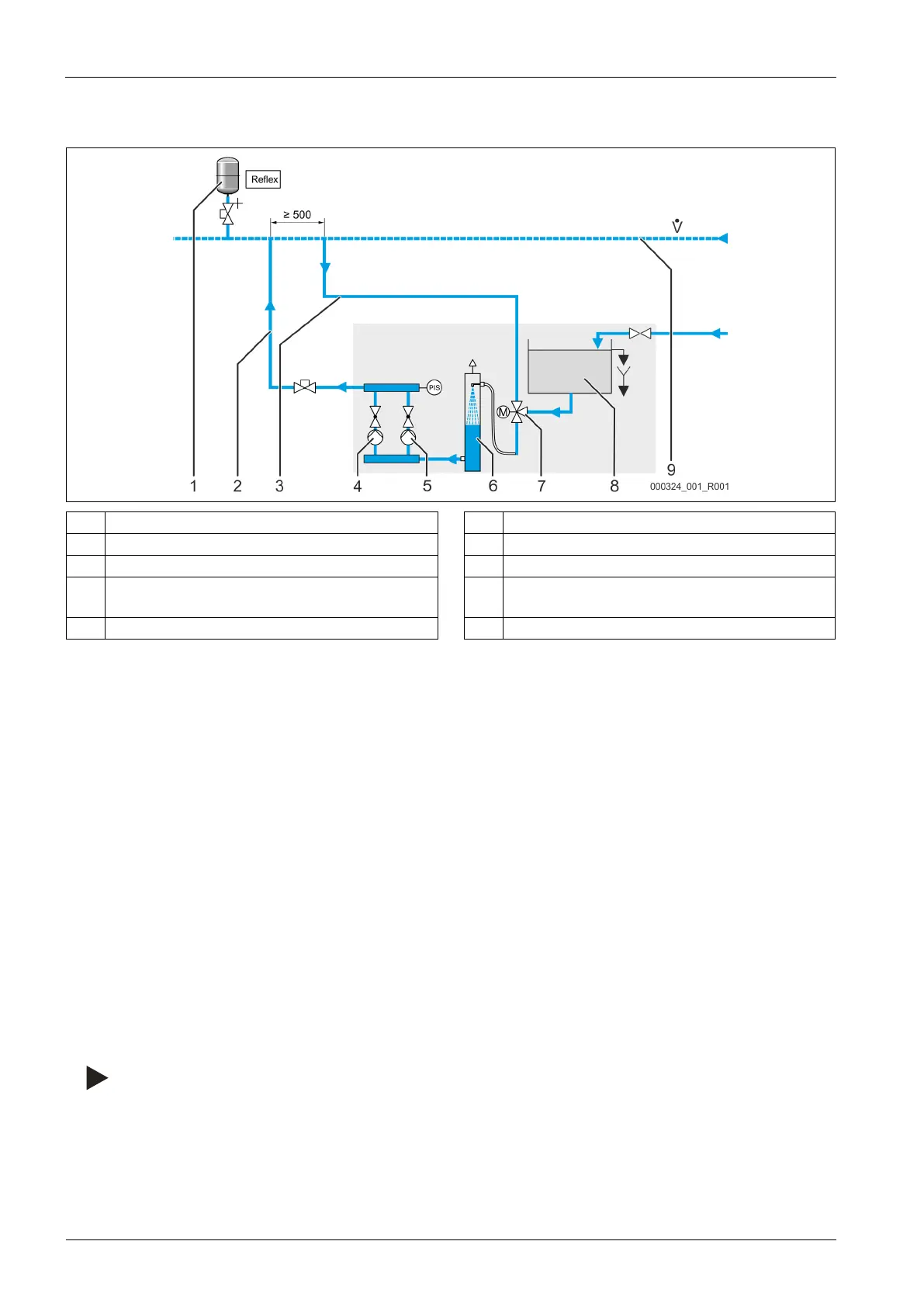
The device within a heating system with static pressure maintenance via a diaphragm expansion tank.
1 Diaphragm expansion tank 6 Vacuum spray pipe
2 Make-up line 7 Motor ball valve
3 Degassing line 8 System separator vessel
4 Pump 9 Main volume flow
• Return flow
5 Pump PIS Pressure transducer
The device requires a make-up and a degassing line to the facility:
• One make-up line for degassed water from the device to the facility.
• One line for gas-rich water from the system back to the device.
Shut-offs for these lines are pre-installed at the device. The connections of the lines must be made within the main flow volume of the
overall system.
The integration of the degassing lines into the facility system must be realised in the vicinity of the make-up line connection. This
ensures stable pressure conditions.
In facility systems with static pressure maintenance, the pressure transducer in the device monitors the water make-up into the facility
system. When the filling pressure for the facility system drops below the minimum value, the pressure transducer sends a signal to the
device controller. The controller activates the pumps. Water from the vacuum spray pipe is supplied via the make-up line into the facility
system.
Either gas-rich water from the facility system or water from the system separator tank is supplied via the motor ball valve into the
vacuum spray pipe.
• Connect the make-up line in the return and near the connection to the diaphragm expansion tank.
– This ensures that the pressure transducer detects the filling pressure required for make-up.
– For Filling pressure, see chapter 9.2.2 "Service menu" on page 44 .
• For make-up lines with > 10 metres length, use a DN 32 diameter.
– You will avoid an undesired cycling of the make-up.
determine the minimum operating pressure for the required filling pressure.
For Minimum operating pressure,see chapter 7.2 "Determining the P
0
minimum operating pressure for the
controller" on page 29 .
 Loading...