E1/E20/E2/E2 Lite Additional Document 2. Designing the User System
R20UT2937EJ0301 Rev.3.01 Page 14 of 45
Jul 1, 2020
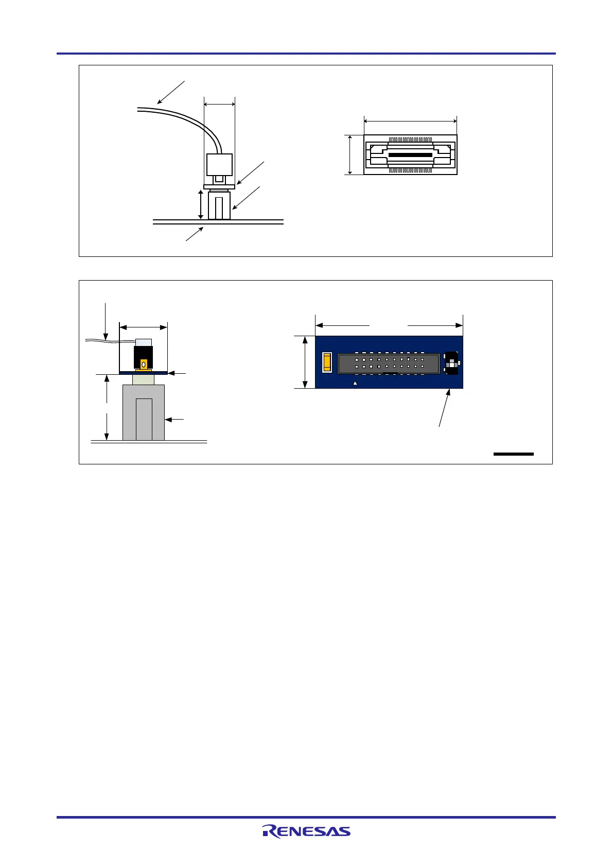
Figure 2-2 Connecting the User System Interface Cable to the 14-Pin Connector of the E20 Emulator
20-pin (1.27-mm pin spacing) user-system
interface cable
13 mm
10.5 mm
User system
14-pin (2.54-mm pin spacing)
connector
7614-6002 or 2514-6002
20-pin (1.27-mm pin
spacing) to 14-pin
(2.54-mm pin spacing)
connector conversion
adapter
10.5 mm
20-pin (1.27-mm pin spacing) to 14-pin
(2.54-mm pin spacing) connector
conversion adapter (top view)
29.0 mm
1
3
Set the switch to position "3"
.
Figure 2-3 Connecting the User System Interface Cable to the 14-Pin Connector of the E2 Emulator
38
-p
i
n t
o 1
4
-p
in
c
on
v
er
si
o
n a
da
p
te
r (
t
op
v
ie
w)
R0E000200CKA00
(
in
c
lu
de
i
n t
h
e E
20
p
ac
ka
g
e)
10
m
m
U
s
er
sy
s
te
m
38-pin user-
sy
s
te
m i
n
te
r
fa
ce
c
ab
le
26.2 mm
9.
4 mm
3
8
-
p
i
n
t
o
1
4
-
p
i
n
conversion adapter
9
.4
m
m
1
4
-p
in
c
on
nector
76
1
4-
60
0
2 o
r
2
51
4
-6
00
2

 Loading...


