E1/E20/E2/E2 Lite Additional Document 3. Notes on Usage
R20UT2937EJ0301 Rev.3.01 Page 37 of 45
Jul 1, 2020
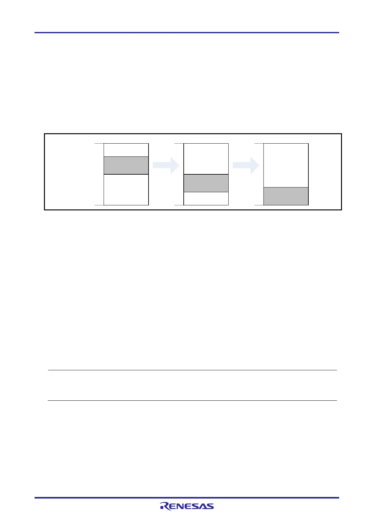
3.3.2 Securing a Stack Area for Debugging
The debugger requires 10 bytes as a stack area for debugging. Since this area is allocated immediately
after the stack area, the address of this area varies depending on the stack increase and decrease. That
is, 10 extra bytes are consumed for the stack area used.
Make sure the stack area for debugging does not exceed the range of the internal RAM space.
Figure 3-2 shows an example in which the stack area has increased with the start address of the
internal RAM space being 0xFFE60.
Stack area for
debugging
10 bytes
Stack area
Available space
in internal RAM
0xFFE60
0xFFEDF
Stack area for
debugging
10 bytes
Stack area
Available space
in internal RAM
0xFFE60
0xFFEDF
Stack area for
debugging
10 bytes
Stack area
0xFFEDF
0xFFE60
Figure 3-2 Variation of Address of Stack Area for Debugging
3.3.3 Setting an On-Chip Debugging Option Byte
This is the area for the security setting to prevent the flash memory from being read by an unauthorized
person.
For settable values, refer to the user's manual for each MCU.
[Setting an on-chip debugging option byte]*
1
Set the on-chip debugging option byte in either of the following ways.
(a) Embed the on-chip debugging option byte at address 0xC3 in the user program.
(b) Set the on-chip debugging option byte by the build tool.
For details on the setting method, refer to the user's manual for the build tool.
If the value of the on-chip debugging option byte set in the device disables on-chip debugging
(OCDENSET = 0), the debugger cannot be started when "No" is selected in the [Permit flash
programming] property of the debugger. If a setting to enable flash programming is made, though the
debugger can be started, the flash memory will be in an erased state when the debugger is started.

 Loading...


