E1/E20/E2/E2 Lite Additional Document 2. Designing the User System
R20UT2937EJ0301 Rev.3.01 Page 21 of 45
Jul 1, 2020
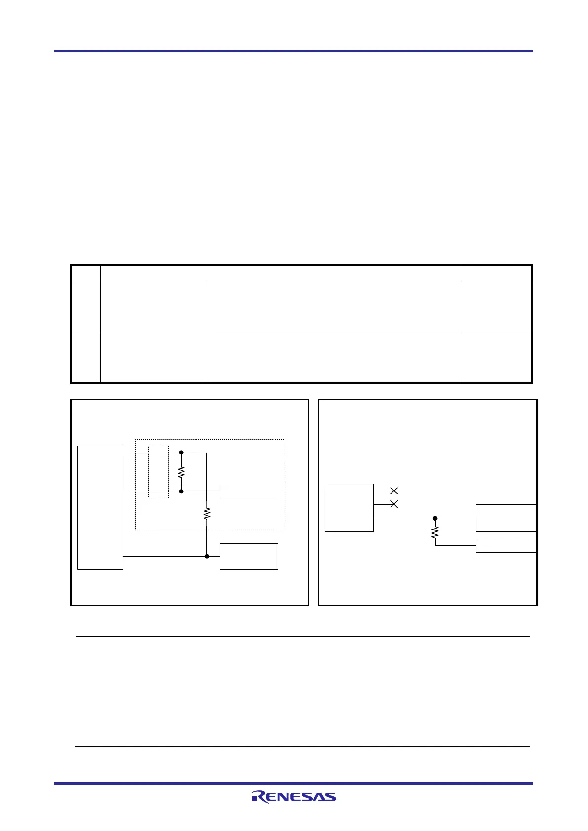
2.5.1 RESET# Pin
The RESET# pin is used by the E1/E20/E2/E2 Lite to monitor the pin state and issue a reset to the
device.
Therefore, a reset signal on the user system is once input to the E1/E20/E2/E2 Lite where it is controlled
by masking and then output to the target device. Connection examples of the RESET# pin section are
shown in Table 2-3 and Figure 2-6 and Figure 2-7.
When flash programming by the programming software is to be performed, the RESET# pin should be
designed so that the reset signal on the user system does not conflict with the reset signal from the
E1/E20/E2/E2 Lite.
Table 2-3 Connection Examples According to the Reset Circuit on the User System
RL78/G1M
RL78/G1N
pin on which the RESET# function is multiplexed is in
use for the reset function.
There is no reset circuit if the section enclosed by the dotted
lines described in note 2 for figure 2-6 is removed.
2 The pin on which the RESET# function is multiplexed is in
use for another function.
(when using the P125/KR1 function which is multiplexed with
RESET#)
Figure 2-7
Reset circuit
6
10,13
RESET_IN
RESET_OUT
4
RSPU
Note 1
14-pin
2.54-mm pitch
connector
MCU
RESET#
<Connection Example 1 of RESET>
(Recommended Circuit)
Note 2
470 to 510 kΩ
1 kΩ
Note 1: It is not necessary in flash programming by the programming software.
Note 2: Connection is unnecessary when there is no reset circuit on the user system.
14-
pin
2.54-mm pitch
connector
MCU
6
10,13
RESET_IN
RESET_OUT
RESET#
4
RSTPU
External circuit
1 kΩ
<Connection Example 2 of RESET>
(when using the P125/KR1/SI01 function which is multiplexed with RESET#)
Figure 2-6 Connection Example 1 of RESET#
Figure 2-7 Connection Example 2 of RESET#
• Do not install capacitors, series resistors, or filters on signal lines; if attempted, correct communication may
not be established. here is an exception, however: capacitors can be inserted between VSS and
RESET_IN.
• The circuits and resistance values listed are recommended but not guaranteed. Determine the circuit design
and resistance values by taking into account the specifications of the target device and noise.
• Securely connect pins 2, 12, and 14 to GND of the user system. These pins are used for electrical
grounding as well as for monitoring of connection with the user system by the E1/E20/E2/E2 Lite. Securely
connect both pin 10 and pin 13.

 Loading...


