E1/E20/E2/E2 Lite Additional Document 2. Designing the User System
R20UT2937EJ0301 Rev.3.01 Page 17 of 45
Jul 1, 2020
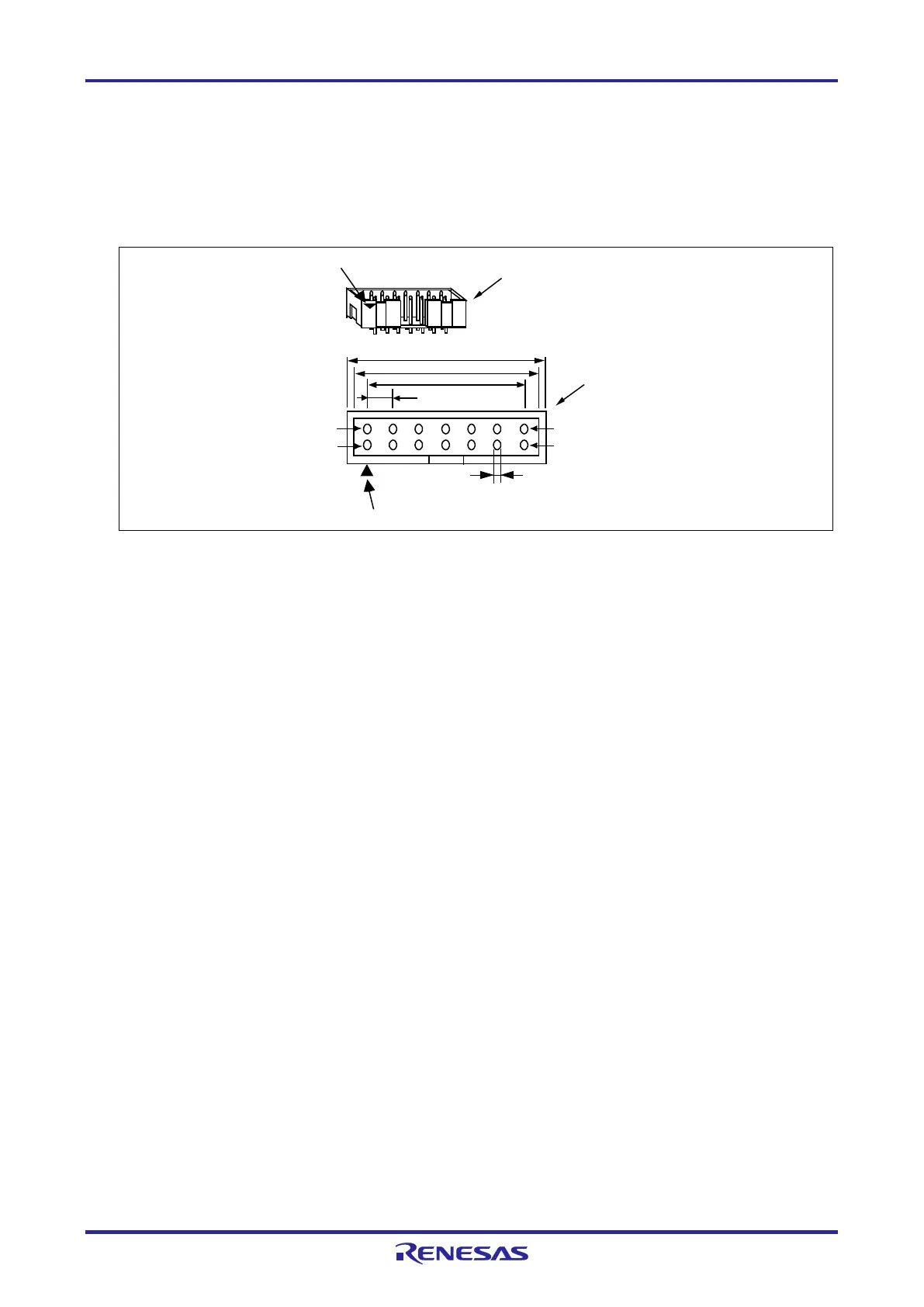
2.3 Pin Assignments of the Connector on the User System
2.3.1 14-Pin Connector Specifications
Figure 2-4 shows the specifications of the 14-pin connector.
Table 2-2 on the following pages shows the pin assignments of the 14-pin connector.
P
i
n 1
ma
r
k
2
5
.
0
2
3
.
0
6
x
2
.
5
4
=
1
5
.
2
4
(
2
.
5
4
)
0
.4
5
P
in
1
P
in
2
P
i
n
1
3
P
i
n
1
4
P
i
n
1
m
a
r
k
C
o
n
n
e
c
t
o
r
C
o
n
n
e
c
t
o
r
(
t
o
p
v
i
e
w
)
U
n
i
t
:
m
m
Figure 2-4 Emulator Connector Specifications (14 Pins)

 Loading...


