E1/E20/E2/E2 Lite Additional Document 2. Designing the User System
R20UT2937EJ0301 Rev.3.01 Page 18 of 45
Jul 1, 2020
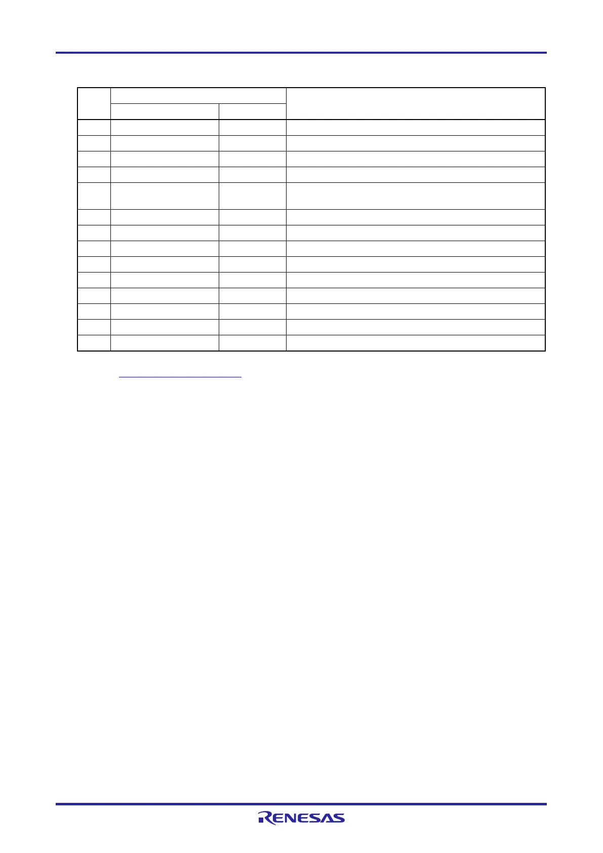
Table 2-2 14-Pin Connector Pin Assignments
Pin
No.
Note
1 R.F.U *5
3 R.F.U *5
This pin is used to pull up the reset line.
5 TOOL0 I/O This pin is used to transmit command/data to the target
device.
This pin is used to input a reset signal from the user system.
7 R.F.U *5
9 EMVDD *6
This pin is used to output a reset signal to the target device.
11 R.F.U *5
13 RESET_OUT *4 Input This pin is used to output a reset signal to the target device.
For details on the programming software, refer to the following.
https://www.renesas.com/RFP
“Input” refers to input from the emulator to the user system and
“output” refers to output from the user system to the emulator.
Securely connect pins 2, 12, and 14 of the connector to GND of the user system. These pins are used
for electrical grounding as well as for monitoring of connection with the user system by the
E1/E20/E2/E2 Lite.
Securely connect both pin 10 and pin 13.
This pin is reserved. Perform the open processing.

 Loading...


