E1/E20/E2/E2 Lite Additional Document 2. Designing the User System
R20UT2937EJ0301 Rev.3.01 Page 28 of 45
Jul 1, 2020
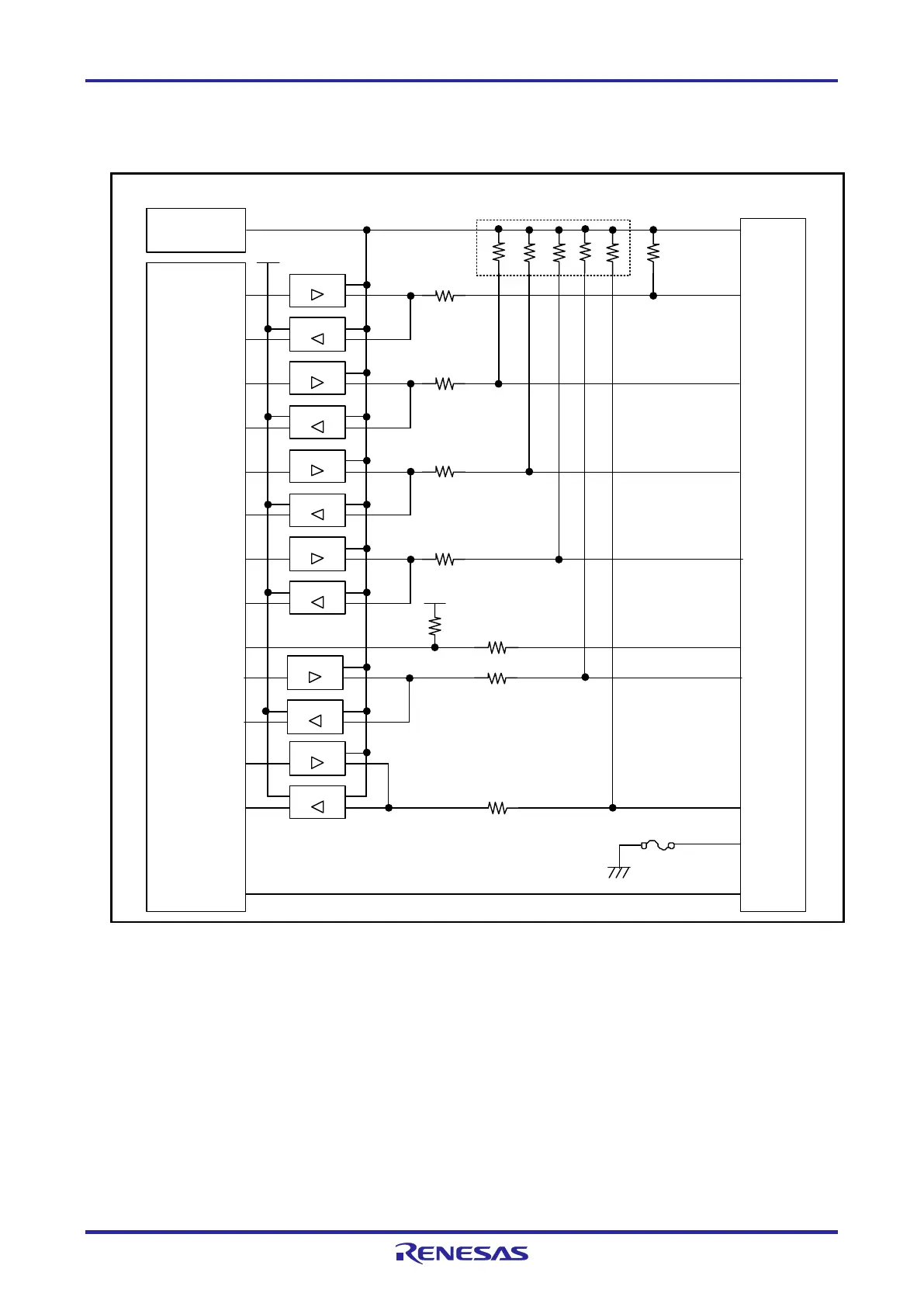
2.6.4 Internal Circuits of the E2 Lite (when the RL78 Family is Connected)
Figure 2-12 shows the internal circuits of the E2 Lite with the RL78 family connected.
Emulator
control
circuit
RSTPU
VDD
4
8
47 Ω
74LVC125
74LVC8T245
3.3 V
TOOL0
5
74LVC125
74LVC125
74LVC8T245
6
RESET_IN
74LVC125
74LVC8T245
47 Ω
10
RESET_OUT
3.3 V
47 Ω
100 kΩ
GND
14
74LVC8T245
13
RESET_OUT
47 Ω
2,12
GND
Power-supply circuit
(only for use in the mode to
supply power to the user
system)
EMVDD
9
47 Ω
47 Ω
74LVC8T245
74LVC125
100 kΩ × 5
1 MΩ
1,3,7,11
74LVC125
74LVC8T245
47 Ω
User-side
connector
Self-recovering
fuse
Figure 2-12 Internal Circuits of the E2 Lite (when the RL78 Family is Connected)

 Loading...


