E1/E20/E2/E2 Lite Additional Document 2. Designing the User System
R20UT2937EJ0301 Rev.3.01 Page 19 of 45
Jul 1, 2020
2.4 Recommended Circuits between the Connector and the MCU
This section shows recommended circuits for connection between the connector and the MCU when the
E1/E20/E2/E2 Lite is in use. For processing of signals, refer to section 2.5, Notes on Connection.
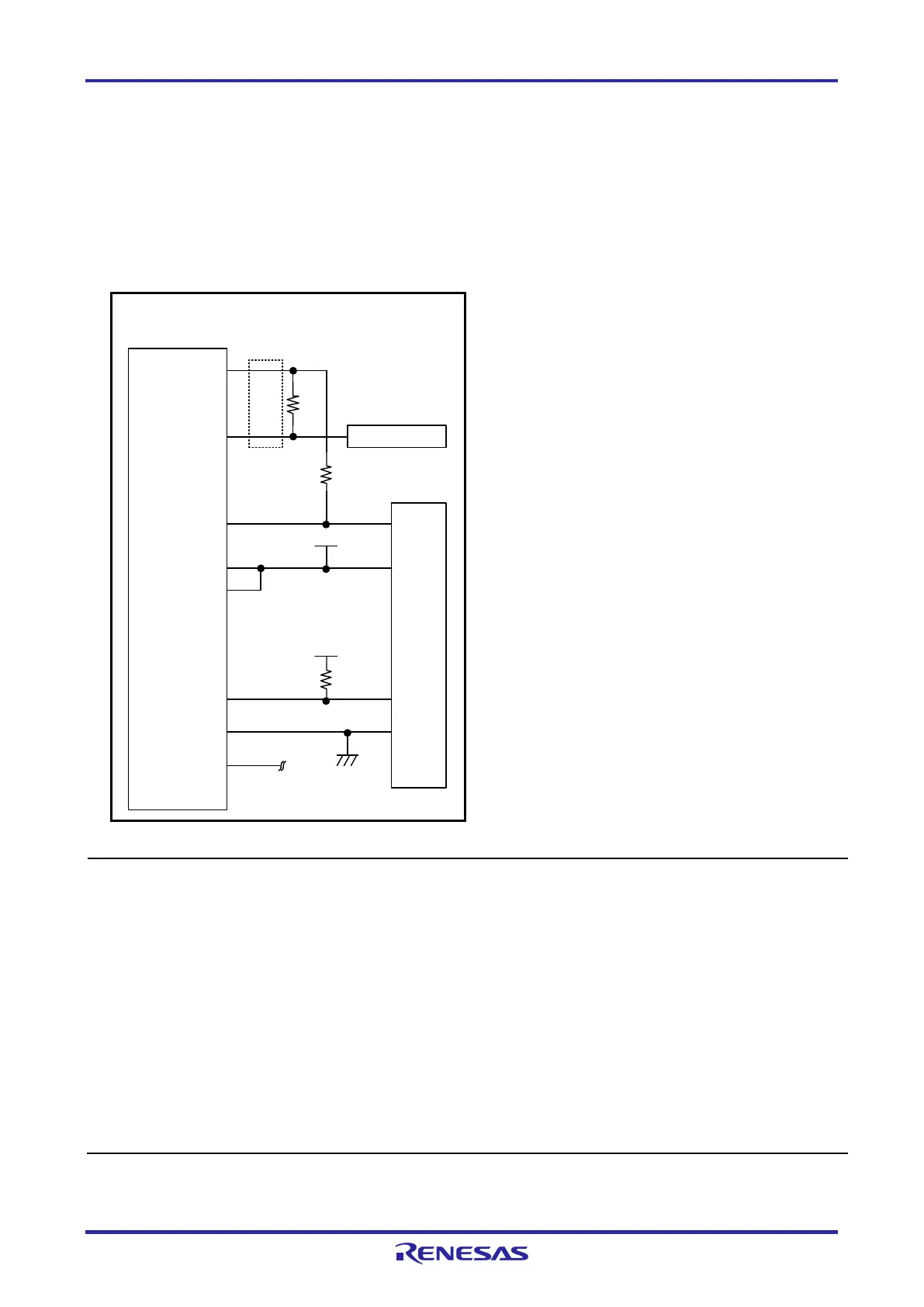
2.4.1 Connection between the 14-Pin Connector and the RL78 Family MCUs
Figure 2-5 shows a recommended circuit for connection between the 14-pin connector and the RL78
family MCUs.
MCU
8
VSS
VDD
9
2,12,14
1,3,4,7,11
5 TOOL0
TOOL0
EVDD
VDD
VSS
R.F.U
470 to 510 Ω
1 kΩ
6
10,13
RESET_IN
RESET_OUT
RESET#
1 kΩ
4
RSTPU
VDD
VDD
Note 1
Note 2
14-pin
2.54-mm pitch
connector
Note 4
Note 3
Note 3
Note 3
Reset circuit
Note 5
Note 3 Note 6
Figure 2-5 Example of Connection between the 14-Pin Connector and the RL78 Family MCUs
Notes: 1 The circuits and resistance values listed are recommended but not guaranteed. Determine the circuit
design and resistance values by taking into account the specifications of the target device and noise.
For flash programming for mass production, perform sufficient evaluation about whether the
specifications of the target device are satisfied.
2 For processing of pins not used by the E1/E20/E2/E2 Lite, refer to the hardware manual for the
device.
3 The recommended circuit for the RESET# pin differs depending on whether the multiplexed functions
are used. For details on how to handle the RESET# pin, also refer to section 2.5, Notes on
Connection.
4 The RESET_IN pin is used only in debugging. It is not necessary in flash programming by the
programming software.
5 Securely connect pins 2, 12, and 14 of the connection to GND of the user system. These pins are
used for electrical grounding as well as for monitoring of connection with the user system by the
E1/E20/E2/E2 Lite.
6 Securely connect both pin 10 and pin 13.

 Loading...


