R8C/1A Group, R8C/1B Group 12. Interrupts
Rev.1.30 Dec 08, 2006 Page 92 of 315
REJ09B0252-0130
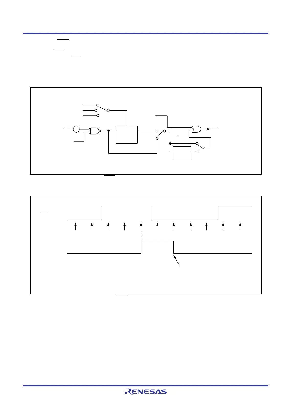
12.2.2 INT0 Input Filter
The INT0 input contains a digital filter. The sampling clock is selected by bits INT0F1 to INT0F0 in the INT0F
register. The INT0
level is sampled every sampling clock cycle and if the sampled input level matches three
times, the IR bit in the INT0IC register is set to 1 (interrupt requested).
Figure 12.12 shows the Configuration of INT0 Input Filter. Figure 12.13 shows an Operating Example of INT0
Input Filter.
Figure 12.12 Configuration of INT0
Input Filter
Figure 12.13 Operating Example of INT0
Input Filter
INT0F0, INT0F1: Bits in INT0F register
INT0EN, INT0PL: Bits in INTEN register
= 01b
INT0
Port P4_5
direction
register
Sampling clock
Digital filter
(input level
matches 3x)
INT0 interrupt
= 10b
= 11b
f32
f8
f1
INT0F1 to INT0F0
INT0EN
Other than
INT0F1 to INT0F0
= 00b
= 00b
Both edges
detection
circuit
INT0PL = 0
INT0PL = 1
INT0 input
Sampling
timing
IR bit in
INT0IC register
Set to 0 by a program
This is an operating example in which bits INT0F1 to INT0F0 in the
INT0F register are set to 01b, 10b, or 11b (digital filter enabled).
 Loading...


