R8C/1A Group, R8C/1B Group 7. Voltage Detection Circuit
Rev.1.30 Dec 08, 2006 Page 52 of 315
REJ09B0252-0130
7.2 Voltage Monitor 1 Reset
Table 7.2 lists the Setting Procedure of Voltage Monitor 1 Reset Associated Bits and Figure 7.8 shows an
Operating Example of Voltage Monitor 1 Reset. To use voltage monitor 1 reset to exit stop mode, set the VW1C1
bit in the VW1C register to 1 (digital filter disabled).
NOTE:
1. When the VW1C0 bit is set to 0 (disabled), steps 3, 4, and 5 can be executed simultaneously (with 1
instruction).
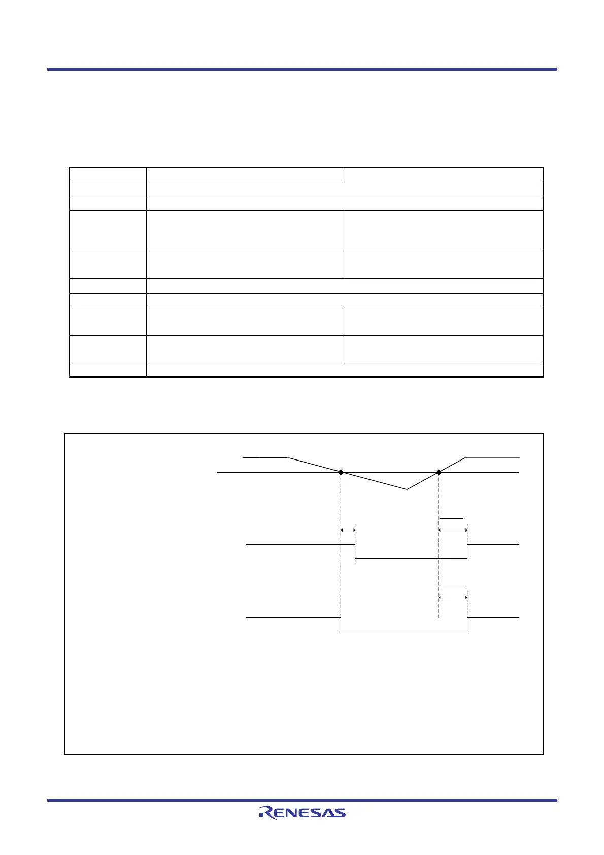
Figure 7.8 Operating Example of Voltage Monitor 1 Reset
Table 7.2 Setting Procedure of Voltage Monitor 1 Reset Associated Bits
Step When Using Digital Filter When Not Using Digital Filter
1 Set the VCA26 bit in the VCA2 register to 1 (voltage detection 1 circuit enabled).
2 Wait for td(E-A)
3
(1)
Select the sampling clock of the digital filter
by bits VW1F0 to VW1F1 in the VW1C
register.
Set the VW1C7 bit in the VW1C register to
1.
4
(1)
Set the VW1C1 bit in the VW1C register to
0 (digital filter enabled).
Set the VW1C1 bit in the VW1C register to
1 (digital filter disabled).
5
(1)
Set the VW1C6 bit in the VW1C register to 1 (voltage monitor 1 reset mode).
6 Set the VW1C2 bit in the VW1C register to 0.
7 Set the CM14 bit in the CM1 register to 0
(low-speed on-chip oscillator on).
−
8 Wait for 4 cycles of the sampling clock of
the digital filter
− (No wait time)
9 Set the VW1C0 bit in the VW1C register to 1 (voltage monitor 1 reset enabled).
Vdet1
(Typ. 2.85V)
Internal reset signal
VCC
The above applies under the following conditions.
• VCA26 bit in VCA2 register = 1 (voltage detection 1 circuit enabled)
• VW1C0 bit in VW1C register = 1 (voltage monitor 1 reset enabled)
• VW1C6 bit in VW1C register = 1 (voltage monitor 1 reset mode)
When the internal reset signal is held “L”, the pins, CPU, and SFR are reset.
The internal reset signal level changes from “L” to “H”, and a program is executed beginning with the address indicated by
the reset vector.
Refer to
4. Special Function Register (SFR), for the SFR status after reset.
1
fRING-S
x 32
Sampling clock of
digital filter x 4 cycles
When the VW1C1 bit is set
to 0 (digital filter enabled).
Internal reset signal
When the VW1C1 bit is set
to 1 (digital filter disabled)
and the VW1C7 bit is set
to 1.
1
fRING-S
x 32
VW1C1 and VW1C7: Bits in VW1C Register
 Loading...


