R8C/1A Group, R8C/1B Group 16. Clock Synchronous Serial Interface
Rev.1.30 Dec 08, 2006 Page 210 of 315
REJ09B0252-0130
16.3.2 Interrupt Requests
The I
2
C bus interface has six interrupt requests when the I
2
C bus format is used and four when the clock
synchronous serial format is used.
Table 16.7 lists the Interrupt Requests of I
2
C bus Interface.
Since these interrupt requests are allocated at the I
2
C bus interface interrupt vector table, determining the factor
by each bit is necessary.
STIE, NAKIE, RIE, TEIE, TIE: Bits in ICIER register
AL, STOP, NACKF, RDRF, TEND, TDRE: Bits in ICSR register
When the generation conditions listed in Table 16.7 are met, an I
2
C bus interface interrupt request is generated.
Set the interrupt generation conditions to 0 by the I
2
C bus interface interrupt routine. However, bits TDRE and
TEND are automatically set to 0 by writing transmit data to the ICDRT register and the RDRF bit is
automatically set to 0 by reading the ICDRR register. When writing transmit data to the ICDRT register, the
TDRE bit is set to 0. When data is transferred from registers ICDRT to ICDRS, the TDRE bit is set to 1 and by
further setting the TDRE bit to 0, 1 additional byte may be transmitted.
Set the STIE bit to 1 (enable stop condition detection interrupt request) when the STOP bit is set to 0.
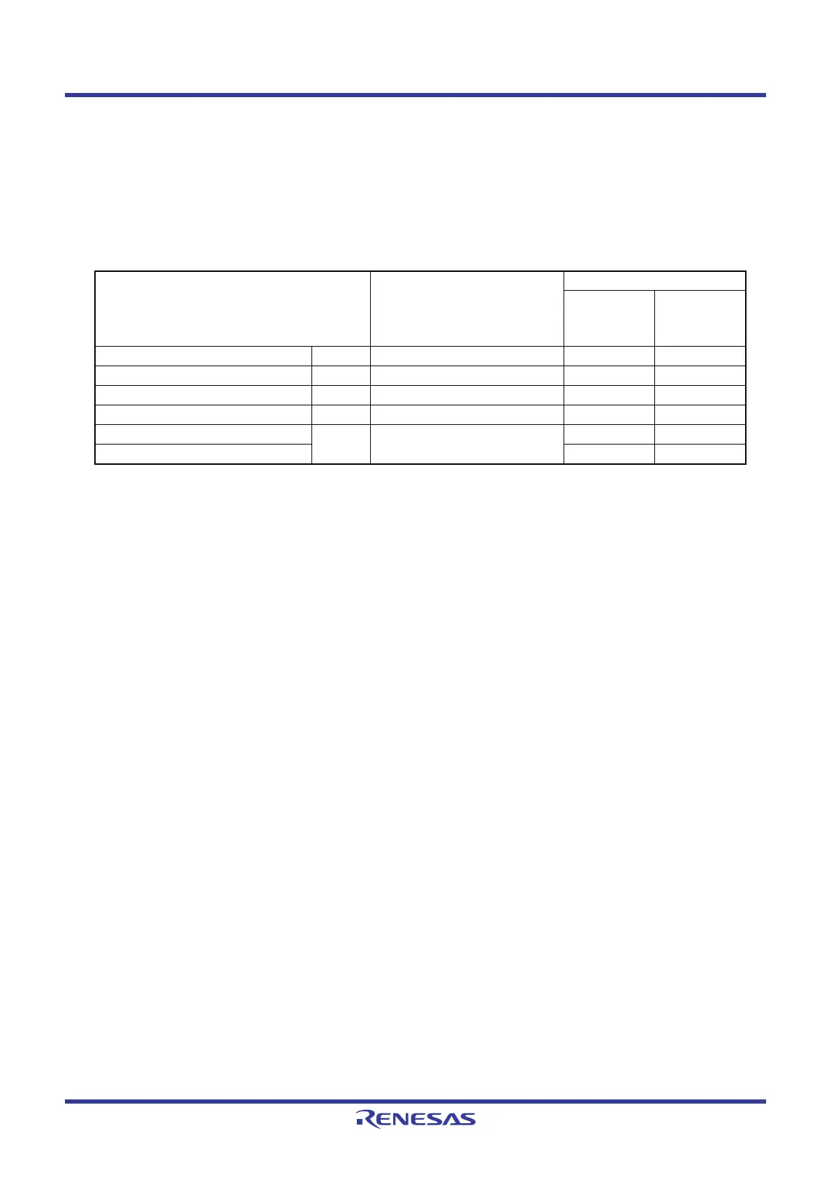
Table 16.7 Interrupt Requests of I
2
C bus Interface
Interrupt Request Generation Condition Format
I
2
C bus
Clock
Synchronous
Serial
Transmit data empty TXI TIE = 1 and TDRE = 1 Enabled Enabled
Transmit ends TEI TEIE = 1 and TEND = 1 Enabled Enabled
Receive data full RXI RIE = 1 and RDRF = 1 Enabled Enabled
Stop condition detection STPI STIE = 1 and STOP = 1 Enabled Disabled
NACK detection NAKI NAKIE = 1 and AL = 1 (or
NAKIE = 1 and NACKF = 1)
Enabled Disabled
Arbitration lost/overrun error Enabled Enabled
 Loading...


