R8C/1A Group, R8C/1B Group 12. Interrupts
Rev.1.30 Dec 08, 2006 Page 95 of 315
REJ09B0252-0130
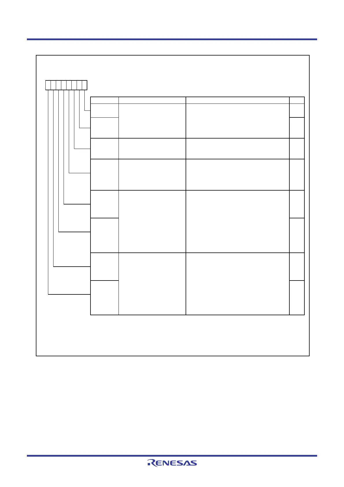
Figure 12.16 TCC1 Register
Timer C Control Register 1
Symbol Address After Reset
TCC1
009Bh 00h
Bit Symbol Bit Name Function RW
INT3
____
filter select bits
(1)
NOTES :
1.
2.
3. When the TCC13 bit is set to 0 (input capture mode), set bits TCC12 and TCC14 to TCC17 to 0.
TCC12
b0
Timer C counter reload select
bit
(2,3)
TCC11
TCC10
TCC13 RW
b3 b2b7 b6 b5 b4 b1
0 : No reload
1 : Set TC register to 0000h w hen compare 1
is matched.
When the TCC00 bit in the TCC0 register is set to 0 (count stops), rew rite the TCC13 bit.
TCC16 RW
TCC17 RW
When the same value from the INT3
____
pin is sampled three times continuously, the input is determined.
Compare 1 output mode select
bits
(3)
b7 b6
0 0 : CMP output remains unchanged even
when compare 1 is matched.
0 1 : CMP output is reversed w hen compare
1 signal is matched.
1 0 : CMP output is set to “L” w hen compare
1 signal is matched.
1 1 : CMP output is set to “H” w hen compare
1 signal is matched.
TCC15 RW
TCC14 RW
Compare 0 output mode select
bits
(3)
b5 b4
0 0 : CMP output remains unchanged even
when compare 0 is matched.
0 1 : CMP output is reversed w hen compare
0 signal is matched.
1 0 : CMP output is set to “L” w hen compare
0 signal is matched.
1 1 : CMP output is set to “H” w hen compare
0 signal is matched.
RW
Compare 0 / capture select bit 0 : Capture select (input capture mode)
(2)
1 : Compare 0 output select
(output compare mode)
RW
RW
b1b0
0 0 : No filter
0 1 : Filter w ith f1 sampling
1 0 : Filter w ith f8 sampling
1 1 : Filter w ith f32 sampling
 Loading...


