R8C/1A Group, R8C/1B Group 8. Processor Mode
Rev.1.30 Dec 08, 2006 Page 56 of 315
REJ09B0252-0130
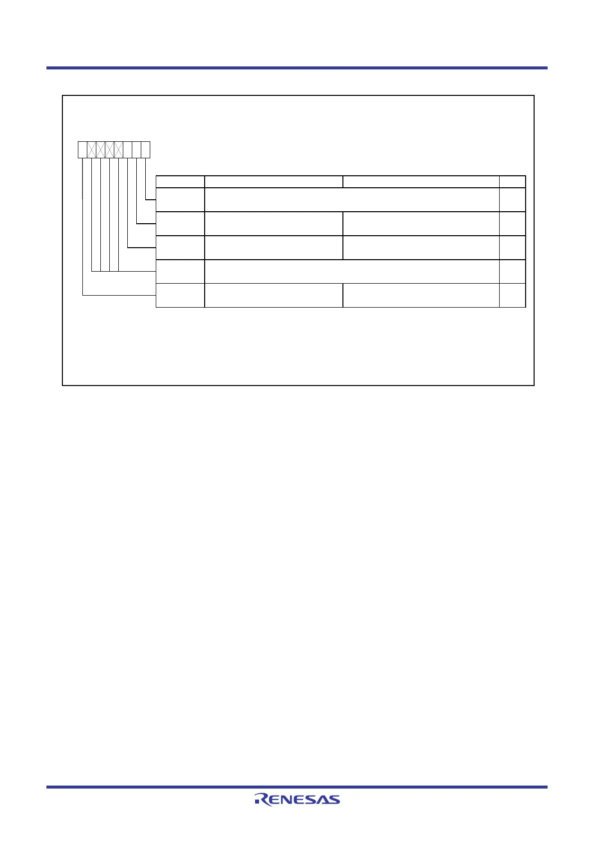
Figure 8.2 PM1 Register
Processor Mode Register 1
(1)
Symbol Address After Reset
PM1 0005h 00h
Bit Symbol Bit Name Function RW
NOTES :
1.
2.
—
The PM12 bit is set to 1 by a program (and remains unchanged even if 0 is w ritten to it).
When the CSPRO bit in the CSPR register is set to 1 (count source protect mode enabled), the PM12 bit is
automatically set to 1.
Reserved bit Set to 0.
Nothing is assigned. If necessary, set to 0.
When read, the content is undefined.
Set the PRC1 bit in the PRCR register to 1 (w rite enable) before rew riting the PM1 register.
—
(b6-b3)
PM12
WDT interrupt/reset sw itch bit
Nothing is assigned. If necessary, set to 0.
When read, the content is 0.
—
(b7)
RW
b3 b2
—
b1 b0
0
0 : Watchdog timer interrupt
1 : Watchdog timer reset
(2)
RW
b7 b6 b5 b4
0
—
(b1)
RW
Reserved bit Set to 0.
—
(b0)
 Loading...


