RZ Family / RZ/G, RZ/A Series 3. Operation Specifications
R01UH0990EJ0101 Rev.1.01 Page 67 of 83
Jul 28, 2022
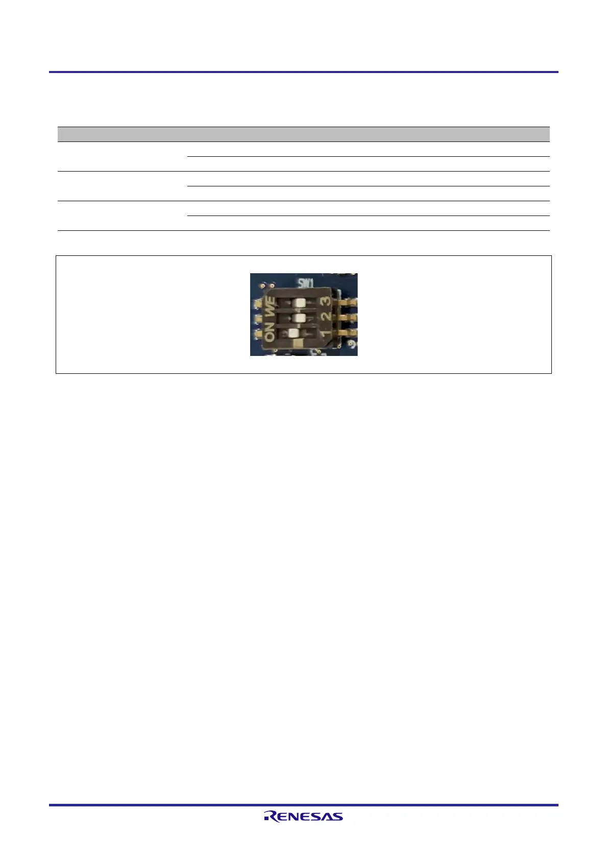
Table 3.6 provides functions of the DIP switch and Figure 3.9 indicates a default terminal state.
Table 3.6 Functions of System Setting DIP Switch (SW1)
Normal operation (default)
Select the eMMC memory (default)
SW1-3
Selection Ethernet0/Peripherals
Select the CAN0, Can1, RSPI1, SSI1 signals (default)
Select the Ethernet0 signals
Figure 3.9 Default Setting of System Setting DIP Switch (SW1)

 Loading...


