Renesas Starter Kit+ for RZ/T2M 6. Configuration
R20UT4939EG0100 Rev. 1.00 Page 36 of 87
Apr 20, 2022
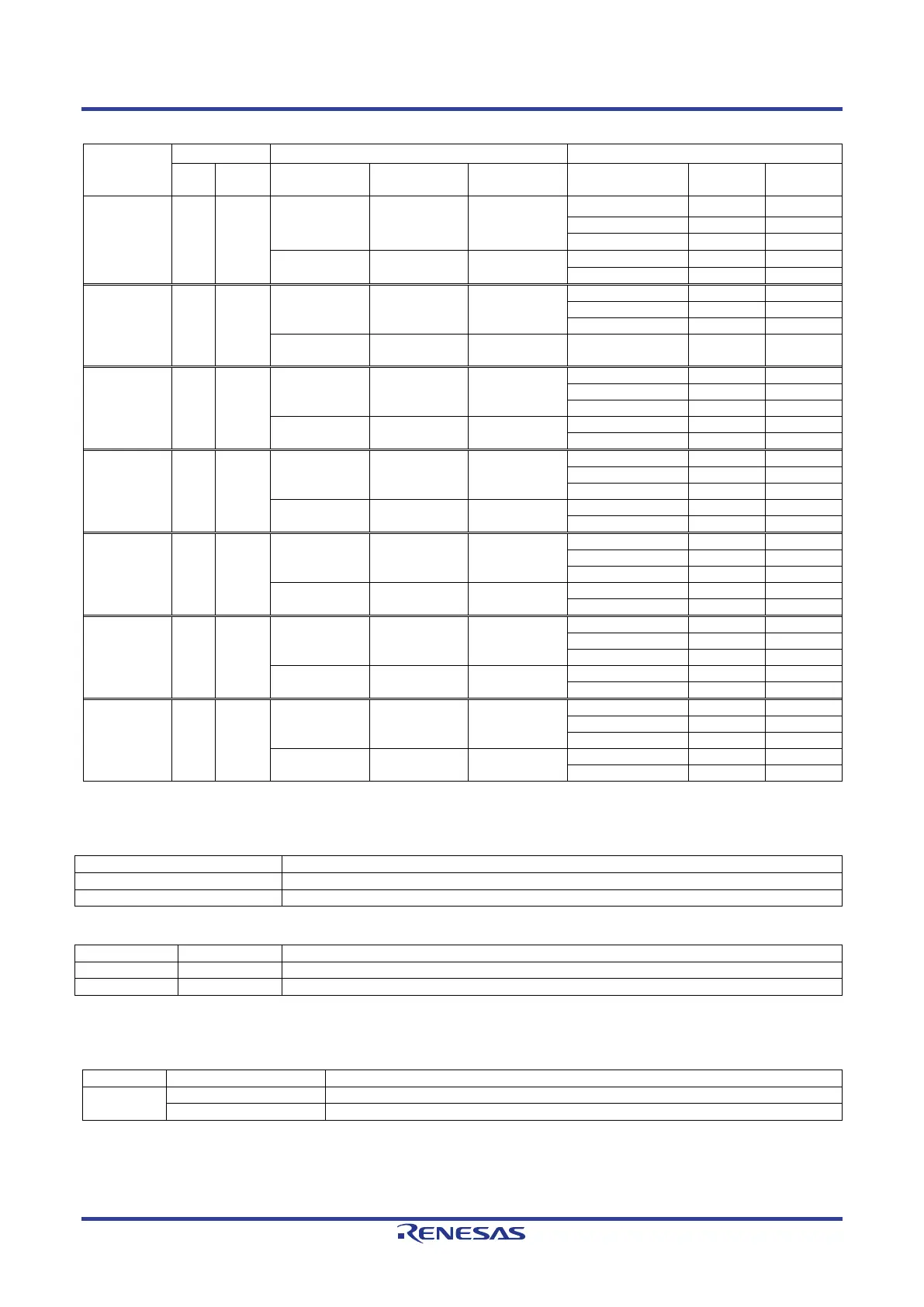
Table 6-7: External Emulator Configuration Option Links (2)
Signal name
Pin
Signal
Fit DNF
Fit DNF
BSC_D06_
TRACE_D6
B7 P21_7
BSC_D06
IC28.47
(SW6-1 = ON)
-
TRACE_D6
-
BSC_A10_M K1 P03_7
BSC_A10
IC29.16
(SW6-1 = ON)
-
TRACE_D5
-
CN9.20 - -
BSC_D04_
TRACE_D4
A7 P21_5
BSC_D04
IC28.50
(SW6-1 = ON)
-
TRACE_D4
-
BSC_D03_
TRACE_D3
A6 P21_4
BSC_D03
IC28.5
(SW6-1 = ON)
-
TRACE_D3
-
BSC_D02_
TRACE_D2
B8 P21_3
BSC_D02
IC28.53
(SW6-1 = ON)
-
TRACE_D2
-
BSC_D01_
TRACE_D1
C8 P21_2
BSC_D01
IC28.2
(SW6-1 = ON)
-
TRACE_D1
-
BSC_D00_
TRACE_D0
B9 P21_1
BSC_D00
IC28.56
(SW6-1 = ON)
-
TRACE_D0
-
Table 6-8 and Table 6-9 below details the function of the switches associated with the External Emulator.
Table 6-8: External Emulator Configuration Switch Settings (1)
Enable the external bus signal.
Enables signals other than the external bus. (CAN, Emulator, I
2
C, etc.)
Table 6-9: External Emulator Configuration Switch Settings (2)
Enable the "M2_POE" signal.
Enable the "TRACE_CTL" signal.
Table 6-10 below details the function of the jumpers associated with the External Emulator.
Table 6-10: External Emulator Configuration Jumper Settings
J9
Enable the External Emulator.
 Loading...


