44
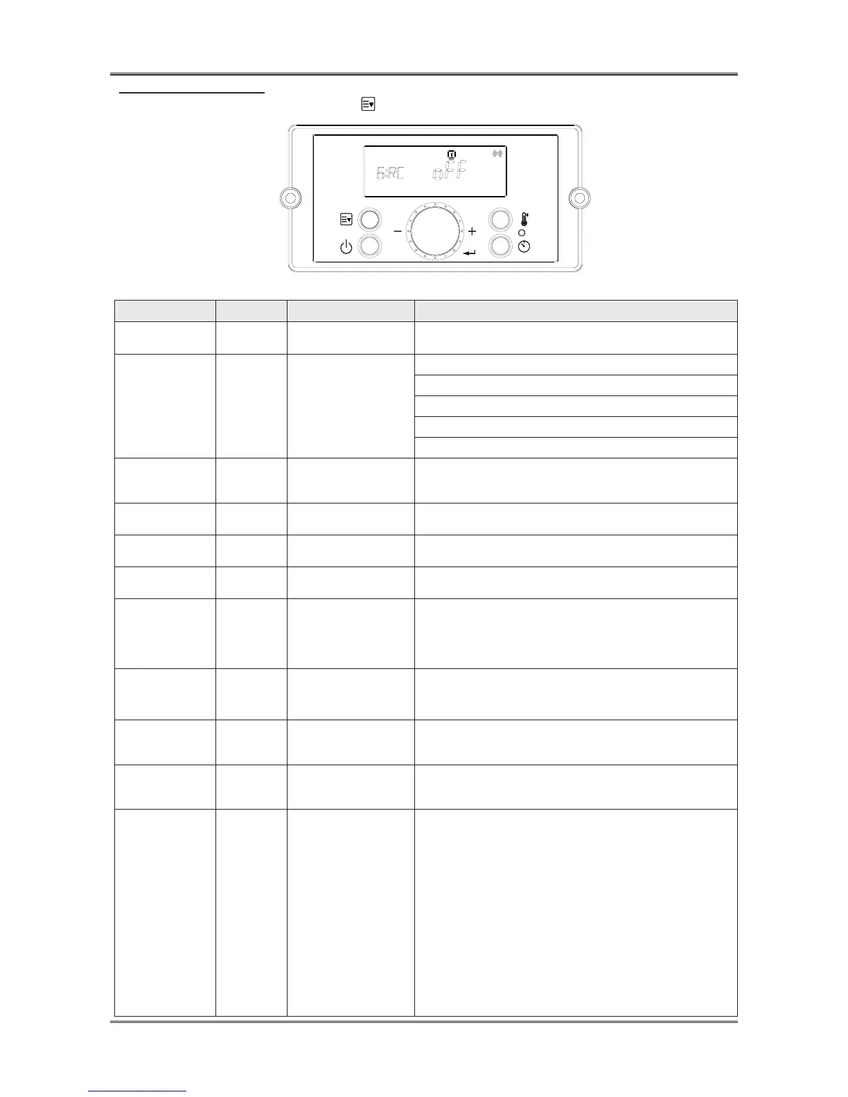
▪ G.INSTALLERMODE
Installer Mode will activate when button is pressed and held for ve seconds while the water heater
display is powered Off.
Figure 38– Installer Mode Screens
Index Default Parameter Description
1:EH N/A Error History
Allows the Installer to View the Unit Error History
Range: E0:XX – E9:XX
2:CE
Clear Error & System
initialize
EHIS :Error History
rH : Burn Hour
bnCY : Burn Cycle
PPHr : Pump Running Time
In: System initialize
3:FC GA Unit
Use to choose unit (Water ow rate, Temperature)
LIt
℃
: Liter/minute, Celsius
GAL °F : Gallon/minute, Fahrenheit
4:FH 00 Maximum Fan Speed
Adjusts Maximum Fan Speed
Range: -30 - +30
5:FL 00 Minimum Fan Speed
Adjusts Minimum Fan Speed
Range: -30 -+30
6:RC oFF
Recirculation Pump
Operation
Turns the Recirculation Pump On and Off
Range: On – Pump On, oFF – Pump Off
7:RM Itnl Recirculation Mode
NOTE:
6:RC must be set to On to select 7:RM
Sets the Recirculation Mode
Range: ItnL – Internal Recirculation
EtnL – External Recirculation / On Demand Kit,
tt24 – Tilte 24 Mode, bYPS-Cross over
8:RT HI-2
Recirculation
Temperature
Sets Recirculation Temperature
Range: LO – Low Temperature, HI-1 – Middle Temperature,
HI-2 – High Temperature
9:HT HI-2 Hot Water Temperature
Sets Hot Water Temperature
Range: LO – Low Temperature, HI-1 – Middle Temperature,
HI-2 – High Temperature
10:IV 6 Prevent Ignition
Temporarily disables the water heater from igniting for a set period
of time.
Range: 0 – 20 Minutes
11:HA 0 - 2 High Elevation Mode
This water heater may be installed at elevations up to 10,000 feet
and operate on either Natural or LP. The appliance will de-rate by 4%
for each 1,000 feet above sea level.
Select the appropriate installation location as described below.
Selects Installation Location for Proper Water Heater Operation at
Altitude:
0-2 for installation locations from sea level to 2,000 feet
2-5 for locations from 2,000 to 5,000 feet
5-8 for locations from 5,000 to 8,000 feet
Default: 0 – 2
NOTE: Use a combustion analyzer to ensure CO and CO
2
are
within the ranges shown in this manual. Adjust the offset screw in
the clockwise (positive) or counterclockwise
(negative) directions (approximately 1/8 turn) if the measured CO
2
value on LOW FIRE
is out of range.
Chapter3HowtoUseTheControlPanel
 Loading...