Rockwell Automation Publication 520-UM001I-EN-E - July 2016 45
Installation/Wiring Chapter 1
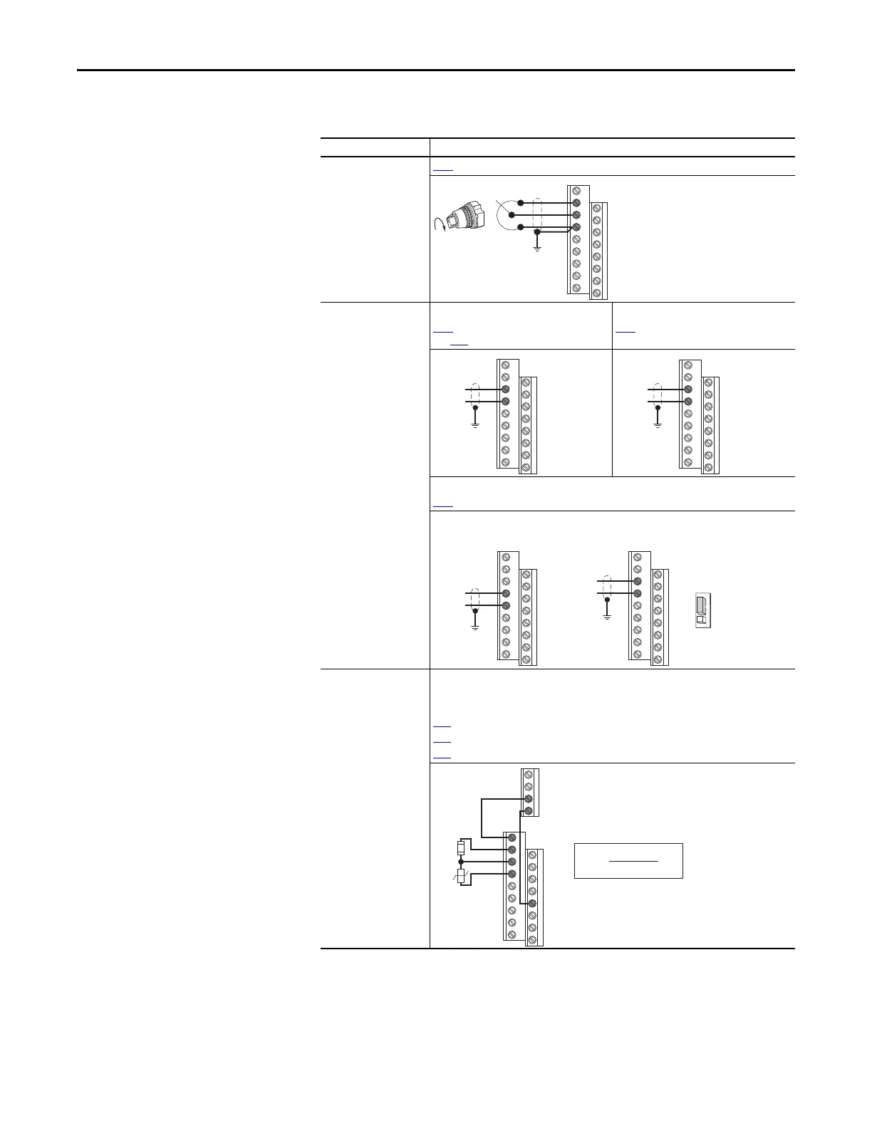
I/O Wiring Examples
I/O Connection Example
Potentiometer
1...10k Ω Pot.
Recommended
(2 W minimum)
P047
[Speed Reference1] = 5 “0-10V Input”
Analog Input
0-10V, 100k Ω impedance
4-20 mA, 250 Ω
impedance
Bipolar
P047 [Speed Reference1] = 5 “0-10V Input”
and t093 [10V Bipolar Enbl] = 1 “Bi-Polar In”
Unipolar (Voltage)
P047 [Speed Reference1] = 5 “0-10V Input”
Unipolar (Current)
P047
[Speed Reference1] = 6 “4-20mA Input”
Analog Input, PTC
For Drive Fault
Wire the PTC and External Resistor (typically matched to the PTC Hot Resistance) to I/O
Terminals 12, 13, 14.
Wire R2/R3 Relay Output (SRC) to I/O Terminals 5 & 11.
t065 [DigIn TermBlk 05] = 12 “Aux Fault”
t081
[Relay Out 2 Sel] = 10 “Above Anlg V”
t082
[Relay Out 2 Level] = % Voltage Trip
12
13
14
13
14
±10V
Common
14
15
Common
+
13
14
+
Common
PowerFlex 523 Series BPowerFlex 523 Series A,
PowerFlex 525
4-20 mA
Analog In
0-10V
11
12
13
14
R5
R6
05
%V
Trip
= X 100
R
PTC (hot)
R
PTC (hot)
+ R
e
R
e
R
PTC

 Loading...


