25
Apr. 2014 CUBE-STEX
Test of Volume Control with Notch
Turn the AMPLIFIER volume control with notch at the center of the
panel slowly and verify the reading of LEFT and RIGHT LEDs display.
* If the control is turned either too fast or in the opposite direction, the LED flashes
rapidly. If this happens, return it to the original position and redo the operation.
o: lights, -: goes off
When the control has been turned all the way to the end, execution
automatically advances to the next test item and LEFT, CENTER and
RIGHT LEDs light up.
Volume Control Test
Operate the following controls of (1)-(12) minimum-center-maximum in
numerical order and confirm the all controls work correctly with its LED
lighting and sound from the speaker.
* Operation out of sequence is ignored.
* After detecting all of the minimum, center and the maximum value, test
program advances to test of the next control.
(1) MIC/INSTRUMENT EQUALIZER BASS
(2) MIC/INSTRUMENT EQUALIZER MIDDLE
(3) MIC/INSTRUMENT EQUALIZER TREBLE
(4) MIC/INSTRUMENT REVERB
(5) MIC/GUITAR EQUALIZER BASS
(6) MIC/GUITAR EQUALIZER MIDDLE
(7) MIC/GUITAR EQUALIZER TREBLE
(8) MIC/GUITAR CHORUS/DELAY
(9) MIC/GUITAR REVERB
(10) AUDIO IN VOLUME
(11) LINE IN VOLUME
(12) AMPLIFIER VOLUME
o: lights, -: goes off
The volume level of the speaker sound increases as the control is
operated toward the maximum position, and the pitch rises at the
intermediate position.
When all volume testing has ended, the LEFT, CENTER, RIGHT and
FULL, HALF, LOW LEDs flash.
Switch off the power.
This ends the Test Mode.
Input/Output Level Test
(for Reference)
When components on the circuit board have been replaced, perform this
test.
Items Required
• Level meter
• Signal generator
• Dummy load resistor tool
-4 Ω load resistor
- 1/4-inch phone plug with 47 kΩ load resister
- 1/4-inch stereo phone plug with 100 Ω load resistor
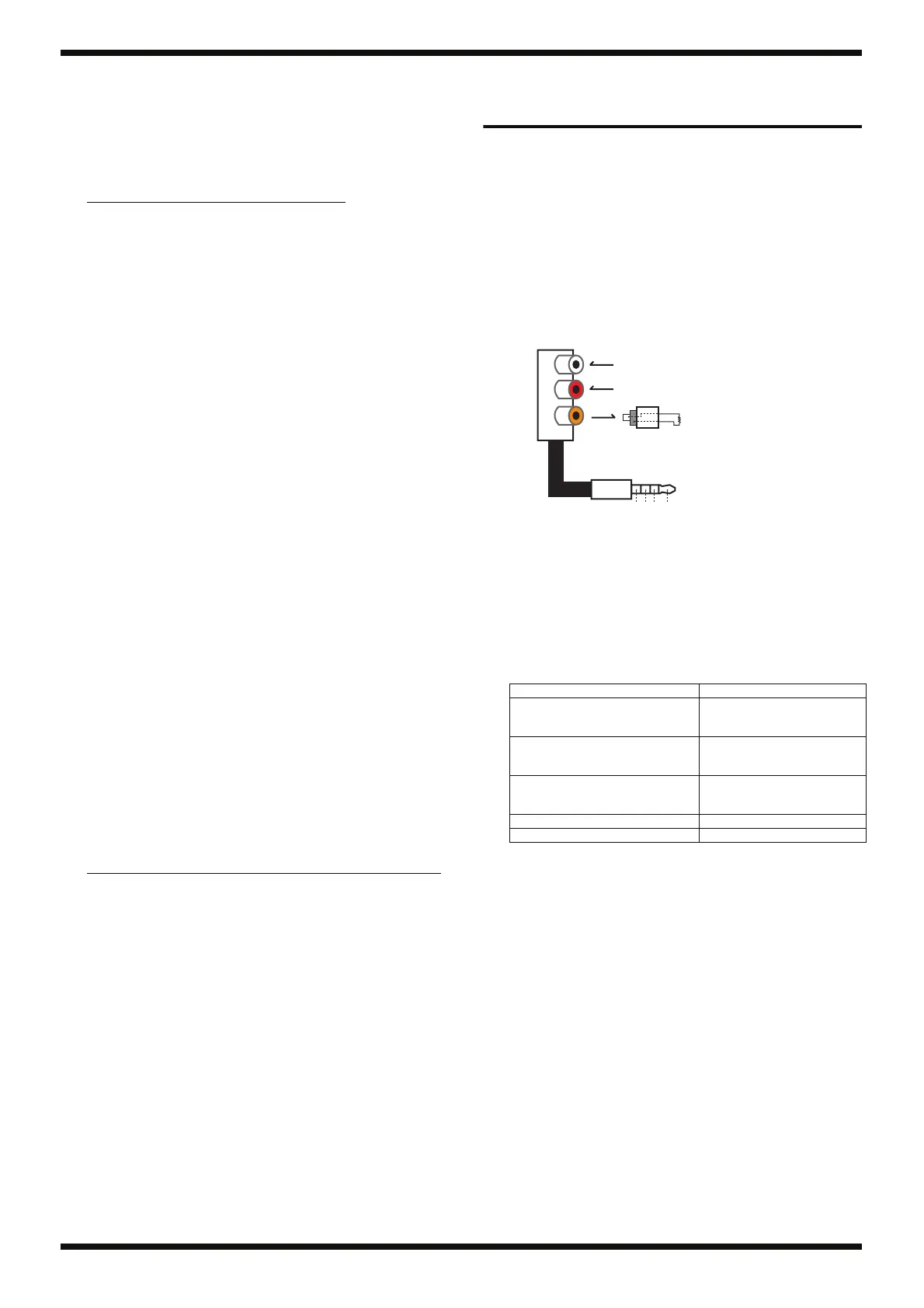
- i-CUBE LINK input/output tool
fig.i-cube-link-jig.eps
Procedure
1. Switch on the power and start the unit in the normal usage state.
2. Make the following settings on the main unit.
Verifying Speaker Output
1. Connect a noise meter and a 4 Ω load resistor to the speaker lines.
2. Set the INPUT SELECT switch to MIC.
3. Connect the signal generator to the MIC/LINE CHANNEL INPUT jack
(unbalanced) and input the following signals.
1-kHz sine wave at -26.0 dBm
4. Verify that signals like the following are output from the speaker lines.
SP OUT L: +15.0 ±1.5 dBm
SP OUT R: +15.0 ±1.5 dBm
5. Set the INPUT SELECT switch to INST.
6. Input the following signals to the MIC/INSTRUMENT INPUT jack.
1-kHz sine wave at +5.5 dBm
7. Verify that signals like the following are output from the speaker lines.
SP OUT L: +15.0 ±1.5 dBm
SP OUT R: +15.0 ±1.5 dBm
Control position LEFT RIGHT
A-GUITAR (6E) o -
ACOUSTIC SIM (5A) - o
CLEAN (4D) o -
CRUNCH (3G) - o
LEAD (2B) o -
MIC (1E) - o
LEAD (2B) o -
CRUNCH (3G) - o
CLEAN (4D) o -
ACOUSTIC SIM (5A) - o
A-GUITAR (6E) o -
Control position LEFT CENTER RIGHT
Minimum
(all the way counterclockwise)
o - -
Center o o -
Maximum
(all the way clockwise)
o o o
Controls and switches Controls and switches position
MIC INSTRUMENT BASS/
MIDDLE/TREBLE, MIC GUITAR
BASS/MIDDLE/TREBLE
Center
MIC INSTRUMENT REVERB,
MIC/GUITAR CHORUS/DELAY,
REVERB
0
AUDIO IN VOLUME, INPUT
VOLUME, AMPLIFIER VOLUME,
LINE IN VOLUME
Center
OUTPUT POWER NORMAL
LINE OUT MODE STEREO LINK
RCA pin jack
AUDIO IN L ch
AUDIO IN R ch
i-CUBE LINK out
1k ohm
i-CUBE LINK out
GND
AUDIO IN R ch
AUDIO IN L ch
RCA pin plug
 Loading...